32 33
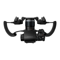
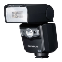
<Adjusting the firing angle> <Using the illuminators>
The illuminators can be used as indicators for three different functions: modeling, AF, and red-
eye reduction.
Modeling lamp function
This function makes it easy to confirm subject s in low light.
AF Illuminator function
With the Olympus Four Thirds System digital SLR camera, the AF illuminators can be turned on
to facilitate focus adjustment when the subject is dark or lacks contrast.
This function can also be defeated in the Custom Setup operation (page 46).
1. Press the Lamp button to light up the illuminators. The
modeling function is activated.
•The default setting for the illuminator lighting period is 30
seconds.
• The lighting period can be set between 1 second and 3
minutes (page 46).
2. The illuminators turn off either when the camera shutter is
released or the Lamp button is pressed again.
Red eye reduction lamp function
With the Olympus Four Thirds System digital SLR camera, the illuminators function as red-eye
reduction lamps that light up for about 1 second to minimize red eyes caused by flash emission.
• It takes about 1 second from the time the illuminators light until the camera’s shutter releases.
Hold the camera firmly during this period to prevent image blur.
• The red eye reduction effect may become less obvious when the subject does not look at the
flash directly from the front, the subject does not look at the pre-flash, the subject is located at a
distance or due to individual properties of the subject.
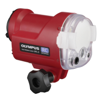
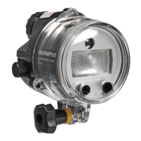
MACRO FLASH CONTROLLER
FC-1
MODE
LAMP
AUTO
CHECK
TEST/
CHARGE
POWER
LIGHT
RATIO GN/
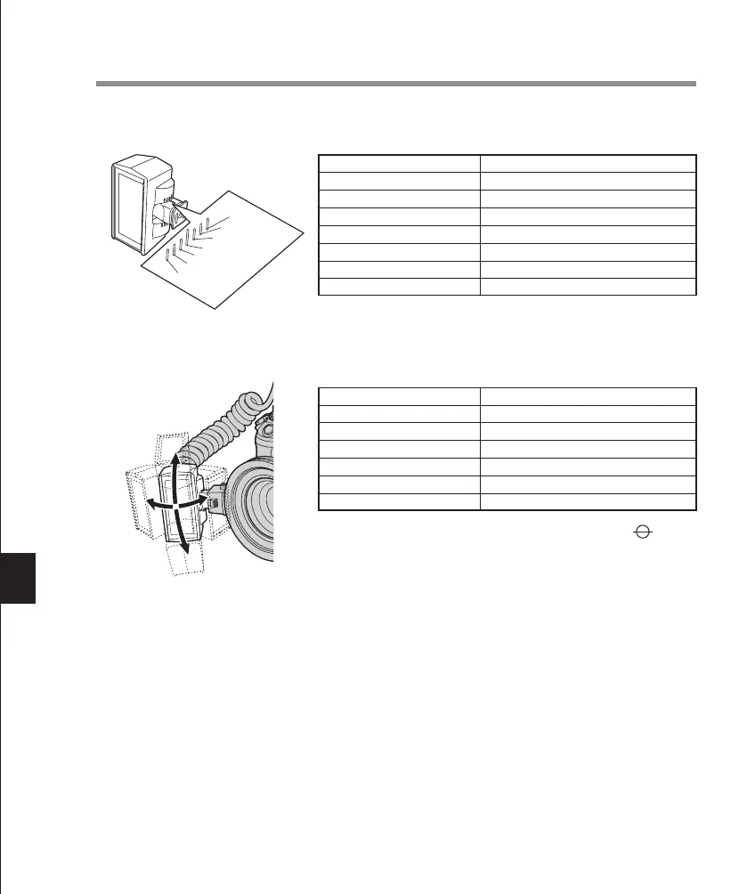
Angle of light emitting section
• Adjustment at the following angles is possible in the up-down direction.
Index position
Up ③
Up ②
Up ①
Horizontal position
Down ①
Down ②
Down ③
Angle from the horizontal position
68°
45°
20°
0°
15°
30°
45°
•
The left-right rotation angle can be adjusted at 45
°
intervals.
Shooting distance*
0.2 m
0.3 m
0.4 m
0.5 m
0.7 m
1.0 m
Angle
30° downward (Down ② index position)
15° downward (Down ① index position)
0°
0°
20ºupward (Up ① index position)
20ºupward (Up ① index position)
*
Distance between the CCD position (marked on the
camera body when you are using the E-1) and the subject.
Index
Up ③
Up ②
Up ①
Horizontal position
Down ①
Down ②
Down ③
Recommended angles: Angles in which light is illuminated on the subject effectively
Left-right rotation angle, from front
• If the system is mounted on the shoe frame, the light emitting section faces the shooting
direction when it set at an upward angle of 20° (Up ① index position).
• Shadows are cast differently and the three-dimensional effect varies depending on the angle.
Also, the effect differs according to the lens used. Set the firing angle according to your shoot-
ing objective.
• The intensity of the light directed at the subject varies according to the angle.
TTL AUTO Flash is fired at optimum exposure, but the light adjustment range varies depend-
ing on the angle.
MANUAL Set the flash ratio after taking some test shots.
Note
Pointing the light emitting section at the lens causes flares and ghosts.
 Loading...