28 29
<Checking the battery power>
1. Tu rn the camera on and then press the Power button to
turn the Twin Flash on.
• The [TWIN] indicator appears on the control panel and
battery charging starts.
Notes:
• If the [RING] or [TWIN] indicator on the control panel
blinks, wait until the blinking stops, then turn the camera
off and re-connect the Ring Flash to the Ring Flash con-
nector (page 47).
• If both the RF-11 Ring Flash and TF-22 Twin Flash are con-
nected, the Twin Flash cannot be turned on by pressing its
Power button. (The Ring Flash and Twin Flash cannot be
connected simultaneously.)
2. Ensure that the Charge lamp lights up.
• Replace the batteries if the time taken for the Charge lamp
to light up is longer than the values specified below.
Alkaline, Ni-Mn, lithium or
Ni-Cd batteries
30 sec.
10 sec.
Memo: Test flash activation
To perform test flash activation, press the Test button.
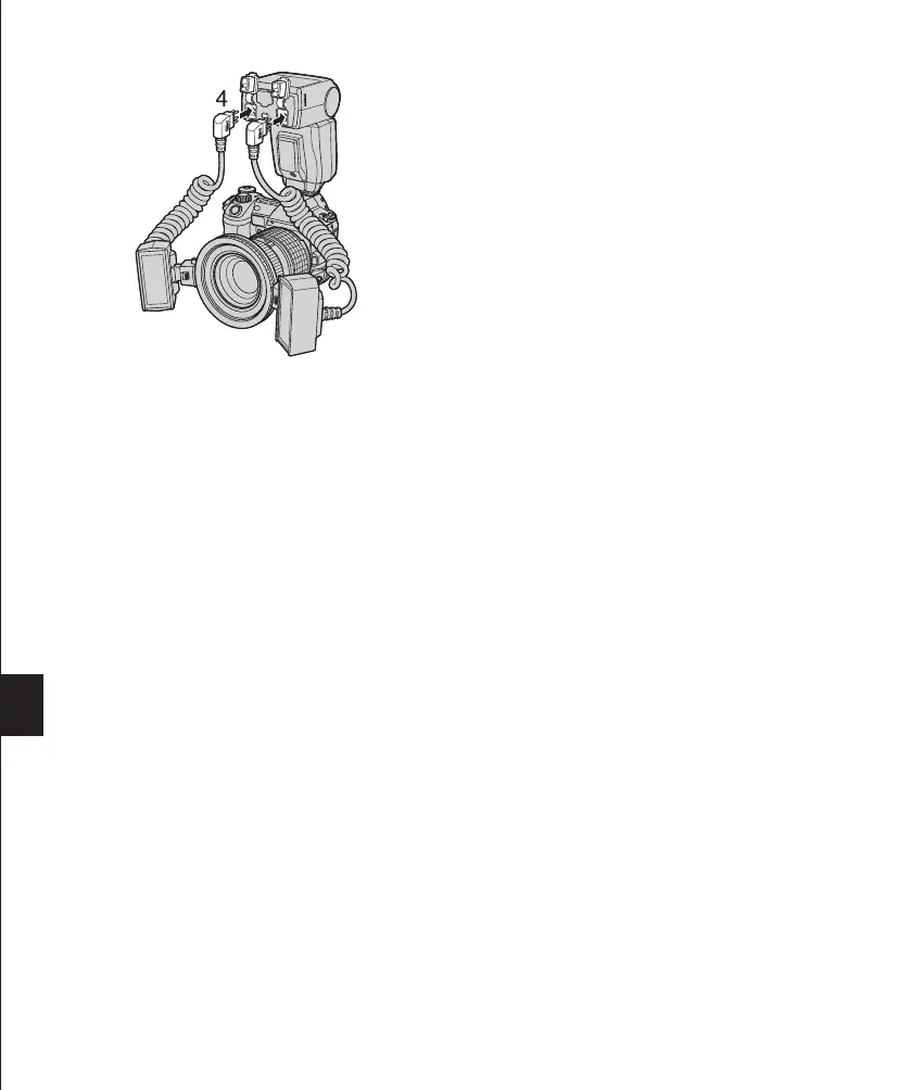
4. Insert the TF-22 Twin Flash connector terminal into the
Twin Flash connector on the FC-1 Macro Flash Controller
until it clicks.
• When unplugging the connectors, be sure to press and
hold the Twin Flash release button. Be sure to attach the
cap after unplugging the connectors.
• Do not pull the cord when plugging or unplugging the con-
nector. Always grasp it by the connector plug. Pulling the
cord could damage the connector wire.
Notes
• Confirm that both the Macro Flash Controller and Twin Flash are off before attaching and removal. Otherwise,
malfunction may result.
• When using only one flash of the Twin Flash, be sure to cap the unused Twin Flash connector.
Be sure to leave the Ring Flash connector capped. Otherwise, the Macro Flash Controller cannot be turned on.
Memo
The Ring Flash and Twin Flash connector terminals are subject to high voltages. To ensure safety, the Macro Flash
Controller is designed so that it cannot be turned on unless one of the flashes is connected to it and all of its unused
connectors are capped.
MACRO FLASH CONTROLLER
FC-1
MODE
LAMP
AUTO
CHECK
TEST/
CHARGE
POWER
LIGHT
RATIO GN/
MACRO FLASH CONTROLLER
FC-1
MODE
LAMP
AUTO
CHECK
TEST/
CHARGE
POWER
LIGHT
RATIO GN/
MACRO FLASH CONTROLLER
FC-1
MODE
LAMP
AUTO
CHECK
TEST/
CHARGE
POWER
LIGHT
RATIO GN/
MACRO FLASH CONTROLLER
FC-1
MODE
LAMP
AUTO
CHECK
TEST/
CHARGE
POWER
LIGHT
RATIO GN/
Ni-Mh batteries
• If the Charge lamp and AUTO CHECK lamp blink alter-
nately, it means that the battery capacity is running low. In
this case, replace the batteries.
 Loading...