UES-40
ISSUE4 1-13 Product Specification
(25) Monopolar/saline cut mode indicators
The lighted indicator corresponds to the cutting mode selected using the switches.
(26) Saline mode indicator
This indicator lights up when saline mode is selected using the switch.
(27) Bipolar coagulation mode indicators
The lighted indicator corresponds to the coagulation mode selected using the switches.
(28) Power switch indicator
This indicator shows that the power is on after the power switch is activated.
(29) CQM indicator
When split type patient plates are attached, the CQM indicator lights up when there is a good
connection with the patient.
(30) Warning indicator
This indicator lights up if equipment problems occur.
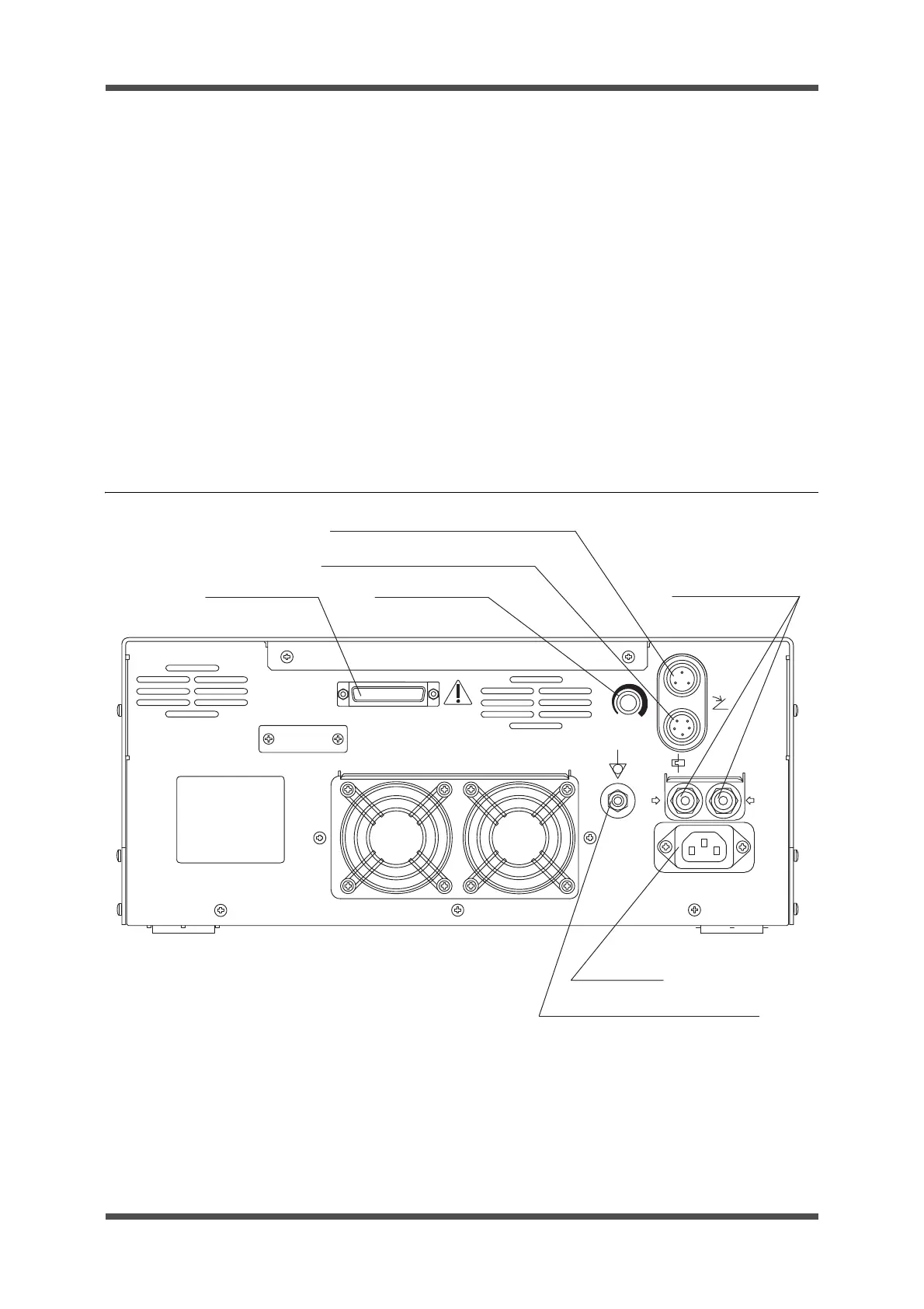
4-2 Rear panel
(1) System port
This system port is for connecting products to expand the functionality of the unit. Connect only
Olympus products.
(2) Volume knob
This knob is for adjustment of the sound output.
SYSTEM
SN
MAJ-1259
MAJ-1258
12A
AC IN
BREAKERS
Foot Switch
VOLUME
12A
Foot Switch
(7) Potential equalization terminal
(1) System port
(5) Circuit breakers
(2) Volume knob
(3) Foot switch port for MAJ-1258
(4) Foot switch connector for MAJ-1259
(6) AC inlet
 Loading...