98
Operation Level Section 5-3
The process value is displayed on the No. 1 display, and nothing is displayed
(blank) on the No. 2 display.
During temperature input, the decimal point position depends on the currently
selected sensor, and during analog input it depends on the “decimal point”
parameter setting.
Related Parameters
Input type: Page 119, Set point upper limit, Set point lower limit: Page 122
(initial setting level)
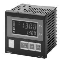
Operation Level
M
M
M
M
M
M
M
M
M
M
M
M
M
M
M
M
M
M
M
a-m
m-sp
0
25
C
25
0
C
sp-m
0
C
ct1
0.0
lcr1
0.0
r-s
run
al-1
0
C
al1h
0
C
al1l
0
C
al-2
0
C
al2h
0
C
al2l
0
C
al-3
0
C
al3h
0
C
al3l
0
C
o
0.0
c-o
0.0
Page Page
Process Value
Process Value/Set Point
Auto/Manual Switch
Heater Current 1
Value Monitor
Leakage Current 1
Monitor
RUN/STOP
Alarm Value 1
Alarm Value 2
Alarm Value 3
MV Monitor (Heating)
MV Monitor (Cooling)
Multi-SP Set Point
Setting
Alarm Value Upper-Limit
1
Alarm Value Lower-Limit
1
Alarm Value Upper-Limit
2
Alarm Value Lower-Limit
2
Alarm Value Upper-Limit
3
Alarm Value Lower-Limit
3
Set Point During SP
Ramp
98
99
99
99
100
100
101
101
101
103
103
102
103
103
102
104
104
104
105
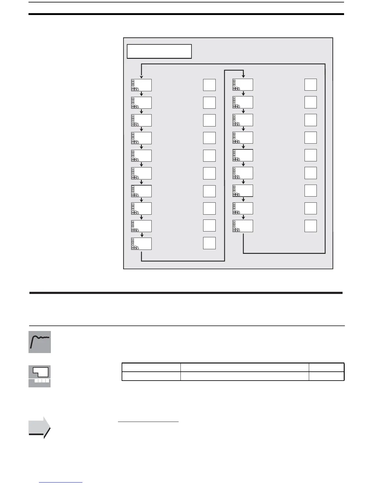
Process Value
The “additional PV display” parame-
ter must be set to ON.
Monitor range Unit
Process value Input indication range (See page 172.) EU
Function
Monitor
See
See
■
 Loading...


