22
Wiring Terminals Section 2-2
E5AZ/EZ
2-2-2 Precautions when Wiring
• Separate input leads and power lines in order to prevent external noise.
• Use AWG24 (cross-sectional area: 0.205 mm
2
) to AWG14 (cross-sec-
tional area: 2.081 mm
2
) twisted-pair cable (stripping length: 5 to 6 mm).
• Use crimp terminals when wiring the terminals.
• Tighten the terminal screws to a torque of 0.74 to 0.90 N·m, except for the
E5CZ-U, which is 0.5 N·m.
• Use the following types of crimp terminals for M3.5 screws.
Note Do not remove the terminal block. Doing so may result in malfunction or fail-
ure.
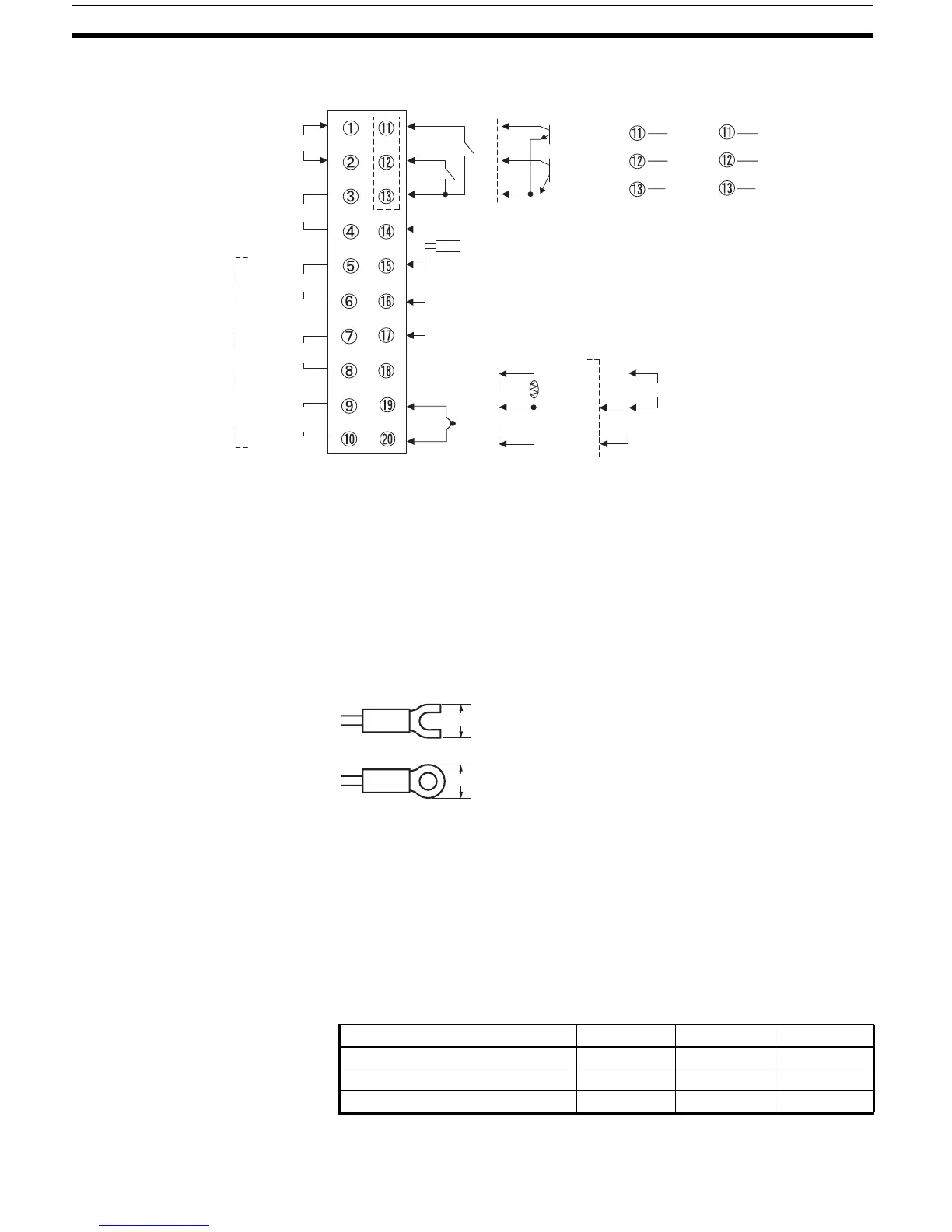
2-2-3 Wiring
In the connection diagrams, the left side of the terminal numbers represents
the inside of the Controller and the right side represents the outside.
Power supply • With the E5CZ, connect to terminals 9 and 10; with the E5CZ-U, connect
to pins 10 and 11; with the E5AZ and E5EZ, connect pins 1 and 2. The
following table shows the specifications.
• Reinforced insulation is applied between the input power supply, the relay
outputs, and other terminals.
−
+
CT1
EV1
EV2
+
+
EV1
EV2
−
+
SD
RD
SG
B(+)
A(−)
RS-232C
E53-AZBOption Units
RS-485
E53-AZ01 E53-AZ03
+
−
A
B
B
+
V
mA
Pt
TC
−
100 to 240 VAC
24 VAC/DC (no polarity)
Relay output 250 VAC,
5 A (Resistive load)
Voltage output
12 VDC, 40 mA
Current output
4 to 20 mA DC
Load 600 Ω max.
Alarm output
(Relay output),
250 VAC, 2 A
(Resistive load)
Input power supply
Control output 1
Alarm output 2
Alarm output 3
Alarm output 1,
HB alarm/HS
alarm/ input
error
Event input
TC/Pt Universal-in
ut Analo
in
ut
One CT
Do not use
Do not use
Do not use
7.2 mm max.
7.2 mm max.
Input power supply E5CZ E5CZ-U E5AZ/EZ
100 to 240 VAC, 50/60 Hz 7.5 VA 6 VA 8.5 VA
24 VAC, 50/60 Hz 5.5 VA 4.5 VA 6 VA
24 VDC (no polarity) 3.5 W 2.5 W 4 W
 Loading...


