I-72 Digital Controller E5CK
Wiring
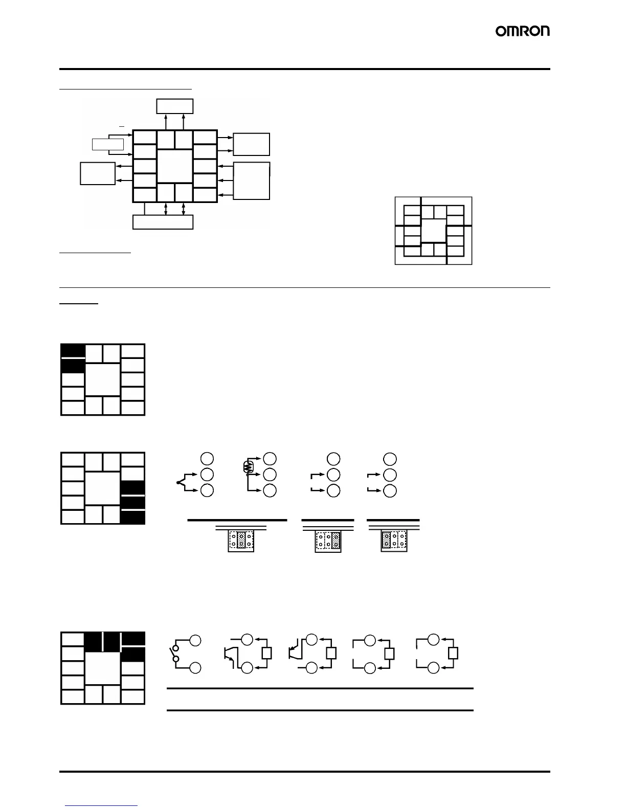
Terminal Arrangement
Precautions
Use ducts to separate input leads and power lines in order to protect
the Controller and its lines from external noise.
Solderless terminals are recommended when wiring the Controller.
Tighten the terminal screws using a torque no greater than 0.78 N·m,
or 8 kgf·cm max. Take care not to tighten the terminal screws too
tightly.
Power Blocks
The E5CK has independent power supplies for each of the terminal
blocks shown below. However, note that the power supplies for
blocks C (exclude relay output) and D are shared for the following
option unit.
• Option unit: E53-CKB or E53-CKF
Wiring
Power Supply
Input 100 to 240 VAC or AC/DC 24 V to terminal numbers 4 and 5 according to the specification. Recommeded 24VDC power supply; eg. OMRON S8VS.
Input
Connect the input to terminal numbers 6 to 8 as follows according to the input type.
Match the inputs with the internal jumper settings for each input type. For thermocouple or platinum resistance thermometer inputs, set the inputs
to a common position (TC/PT) as the temperature input.
Control Output
Terminal numbers 11 and 12 are for control output 1 (OUT1). The five output types and internal equalizing circuits are available according to the
Output Unit.
5
4
3
2
1
10
9
8
7
6
13 14
11 12
AC100
−
240V
~
(AC/DC24V
~
)
OUT1
OUT2
SUB1
OPTION
IN
SOURCE
A
C
5
4
3
2
1
10
9
8
7
6
C
D
B
11 12
13 14
5
4
3
2
1
10
9
8
7
6
13 14
11 12
8
7
6
8
7
6
8
7
6
8
7
6
−
+
−
+
−
+
V
mA
TC⋅PT V
I
5
4
3
2
1
10
9
8
7
6
13 14
11
12
Thermocouple Voltage input Current inputPlatinum resistance
thermometer
5
4
3
2
1
10
9
8
7
6
13 14
11 12
11
12
11
12
L
11
12
L
11
12
L
11
12
L
+v
++++
mA
V
+v
E53-R4R4 E53-V44R4
NPN PNP 0 to 10 V 4 to 20mA
GND
Relay
GND
E53-Q4R4
E53-Q4Q4
E53-Q4HR4
E53-Q4HQ4H
E53-C4R4
E53-C4DR4
−−−−

 Loading...


