H5CR H5CR
9
No-voltage Input Signal Levels
Part Input terminal numbers Power supply terminals Output terminal numbers
number Contact Solid-state
Reset Start Gate Key Protect COM AC (common), DC- AC (hot), DC+ COM NO NC COM LOAD
H5CR-B 7 8 9 10 6 1 2 3 4 5 3 4
H5CR-S
H5CR-L 3 4 — — 1 2 7 8 6 5 8 6
1. High level
Transistor ON
No-contact Residual voltage: 2 V max.
input Impedance when ON:
1 kΩ max.
2. Low level
Transistor OFF
Impedance when OFF:
100 kΩ min.
Contact Use contacts which can
input adequately switch 2 mA
at 5 V.
Operation
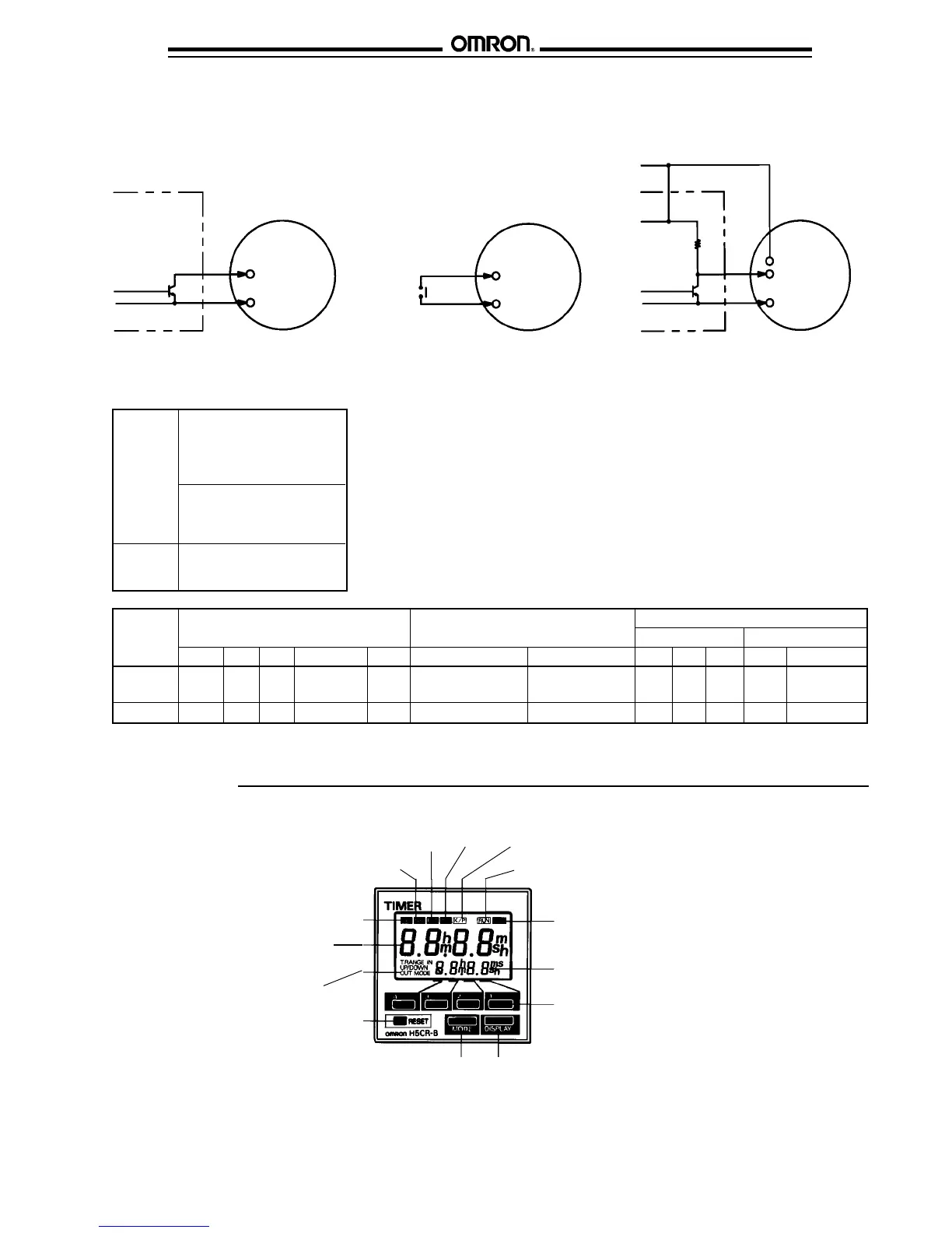
■ NOMENCLATURE
Signal
input
indicator
Reset
indicator
Gate
indicator*
Timing
indicator
Key protection
indicator*
Control
output
indicator
Set value
(value in
set function mode)
Increment
keys (1–4)
Display
key
Mode
key
Power
indicator
Reset
key
Mode
indicator
Present value
(Nonsignificant
zeros suppressed)
* Key protection indicator and gate indicator are
not included in the H5CR-L.
■ INPUTS
The inputs of the H5CR are no-voltage (short circuit or open) inputs.
No-contact Input
(NPN Transistor)
Contact Input
No-contact Input
Sensor
Timer
Input use 0 V
Timer
Start signal,
reset, etc.
Input use 0 V
(30 V max.)
+ V
Sensor
Timer
12 VDC
Start signal,
reset, etc.
Input use 0 V
High: contact ON
High: transistor ON High: transistor ON
Start signal,
reset, etc.
 Loading...