4 Safety Function Blocks
4 - 16
NX-series Safety Control Unit Instructions Reference Manual (Z931)
Introduction
• This FB controls a safety output and monitors actuator control.
• This FB monitors the initial status of the actuator through feedback signals (S_EDM1 and
S_EDM2) before the actuator is activated by the FB.
• After the actuator is activated by this FB, the FB also monitors the actuator’s switched status
(MonitoringTime).
• Two single feedback signals must be used for an exact diagnosis of the connected actuators. A
common feedback signal from the two connected actuators must be used for a restricted yet sim-
ple diagnostic function of the connected actuators. To achieve that, you must connect the com-
mon signal to both the S_EDM1 and S_EDM2 parameters. Therefore, S_EDM1 and S_EDM2 will
be controlled by the same signal.
• The switching device for which the safety function is used must be selected from the category that
was determined by risk assessment.
• Activate the S_StartReset input only when you can ensure that no hazardous state will occur as
the result of starting the Safety CPU Unit.
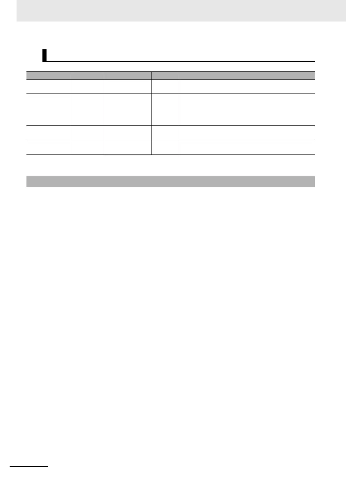
Output Variables
Variable Data type Valid range Default Description
Ready BOOL TRUE or FALSE FALSE Refer to Safety FB Common Output Variables on page
4-4.
S_EDM_Out SAFEBOOL TRUE or FALSE FALSE Controls the actuator. It monitors the result with the feed-
back signal S_EDMx.
FALSE: Disables the connected actuator.
TRUE: Enables the connected actuator.
Error BOOL TRUE or FALSE FALSE Refer to Safety FB Common Output Variables on page
4-4.
DiagCode WORD Depends on state
code.
16#0000 Refer to Safety FB Common Output Variables on page
4-4.
Function

 Loading...


