19
Wiring the Control Input Signals for the Servo Drives
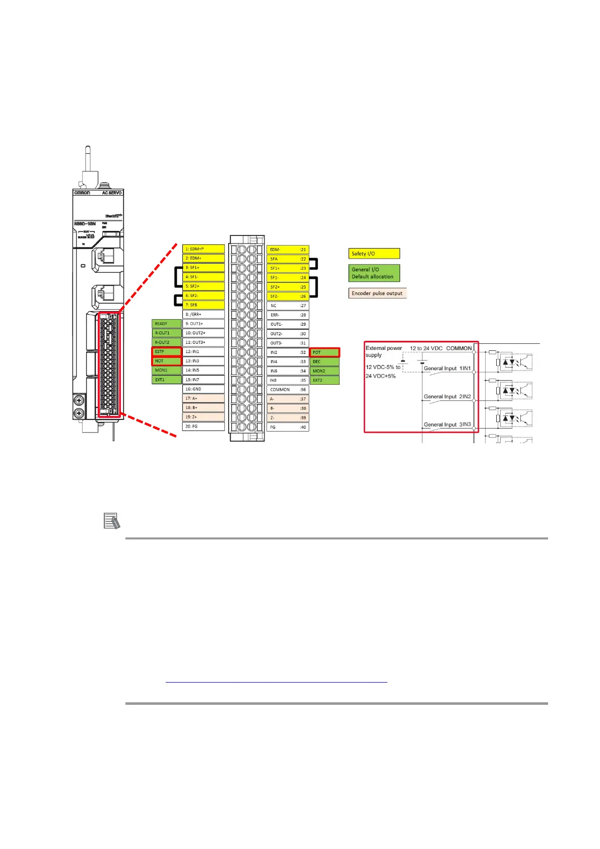
Wire the control input signals for the Servo Drive using the R88A-CN101C Control I/O connector
(CN1).
For details on wiring, refer to the AC Servomotors/Servo Drives 1S-series with Built-in EtherCAT
Communications User's Manual (Cat. No. I586).
*Control I/O Connector (CN1):
Used for command input signals, I/O signals, and as the safety device connector. The short-circuit wire is installed on
the safety signals before shipment.
Additional Information
• If you use the default Servo parameters, you must wire the immediate stop input, negative drive
prohibit input, and the positive drive prohibit input.
If these inputs are not wired, the CPU Unit will remain in the drive prohibit signal and emergency stop
signal detected state, and a minor fault level Controller error will occur. The minor fault level Controller
errors that will occur are an Immediate Stop Input Error and a Drive Prohibition Input Error. (The event
codes are 68220000 and 64E30000.)
• If the above signals are temporarily not wired while commissioning the system, you can temporarily
change the Servo parameters to prevent these errors from occurring in the CPU Unit.
Refer to A-1 Settings When Control Input Signals Are Not Wired
for details on the settings that you
must change in this case.
When using the default Servo parameters, please wire the
immediate stop input (ESTOP), negative drive prohibit input
(NOT), and the positive drive prohibit input (POT).

 Loading...

