7 Applied Functions
7 - 2
G5-series Linear Motors/Servo Drives With Built-in EtherCAT Communications
7-1 Sequence I/O Signals
You can set sequences in various operating conditions.
For the connection of I/O signals and processing of external signals, refer to 3-1-5 Control I/O
Specifications (CN1) on page 3-6.
You can allocate input signal functions to the input pins of the control I/O connector (CN1). In addition,
you can change logic. Refer to Input Signal Allocation Method on page 7-3 for more information
because some signals have allocation limitations.
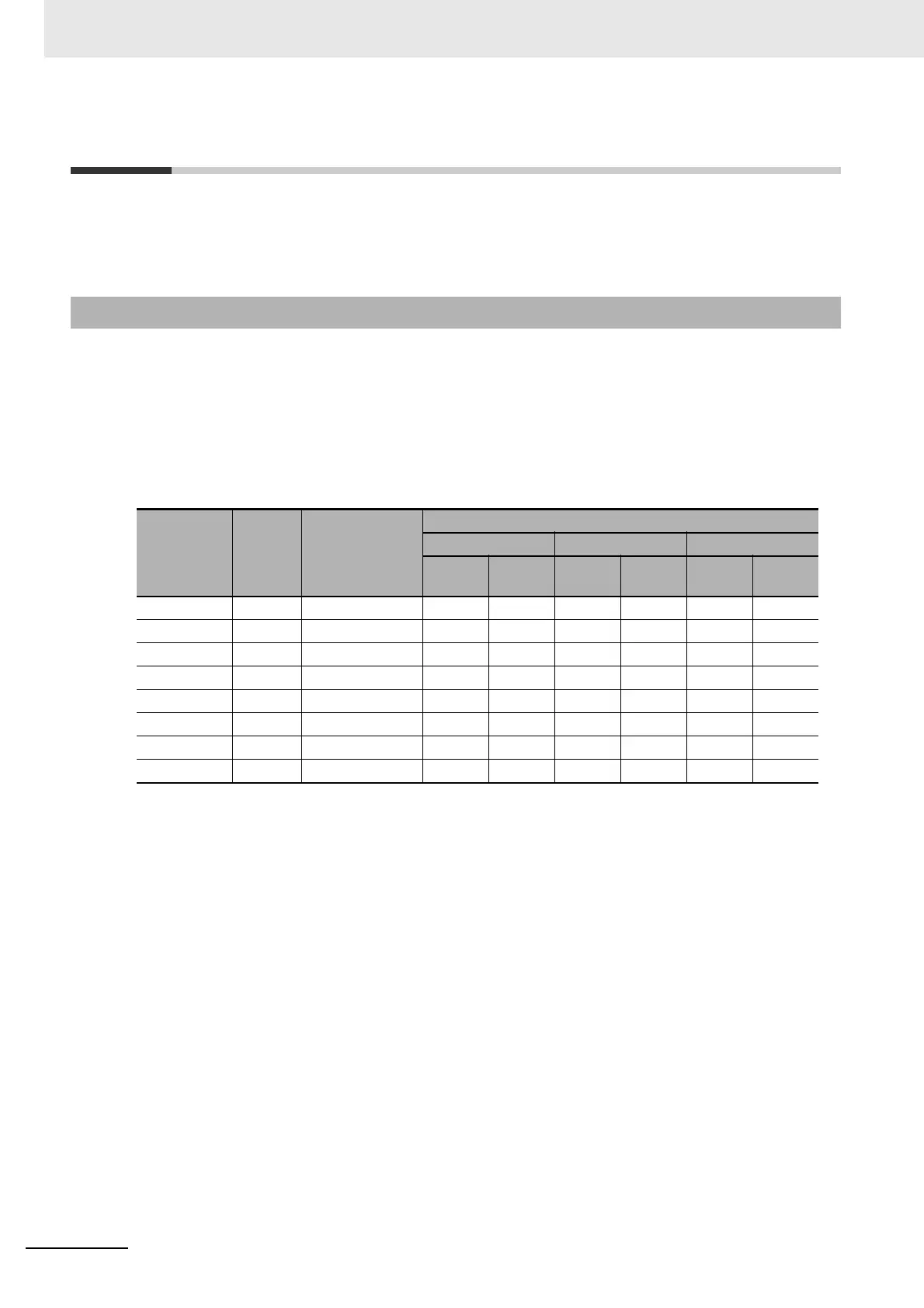
The allocations of the default input signals are as follows.
Refer to Input Signal Allocation Method on page 7-3 to change the allocations.
*1 NO (normally open) and NC (normally close) in the table above refer to the following states.
NO: Disabled (OFF) when signal input is open with COM–
Enabled (ON) when signal input is shorted with COM–
NC: Disabled (OFF) when signal input is shorted with COM–
Enabled (ON) when signal input is open with COM–
7-1-1 Input Signals
Index
Input
signal
Default setting
(hex)
Default setting state
Position control Speed control Force control
Signal
name
Logic
*1
Signal
name
Logic
*1
Signal
name
Logic
*1
3400 hex IN1 0094 9494 hex STOP NC STOP NC STOP NC
3401 hex IN2 0081 8181 hex POT NC POT NC POT NC
3402 hex IN3 0082 8282 hex NOT NC NOT NC NOT NC
3403 hex IN4 0022 2222 hex DEC NO DEC NO DEC NO
3404 hex IN5 002B 2B2B hex EXT3 NO EXT3 NO EXT3 NO
3405 hex IN6 0021 2121 hex EXT2 NO EXT2 NO EXT2 NO
3406 hex IN7 0020 2020 hex EXT1 NO EXT1 NO EXT1 NO
3407 hex IN8 002E 2E2E hex MON0 NO MON0 NO MON0 NO
 Loading...
