9 - 55
9 Servo Parameter Objects
G5-series Linear Motors/Servo Drives With Built-in EtherCAT Communications
9-7 Special Objects
9
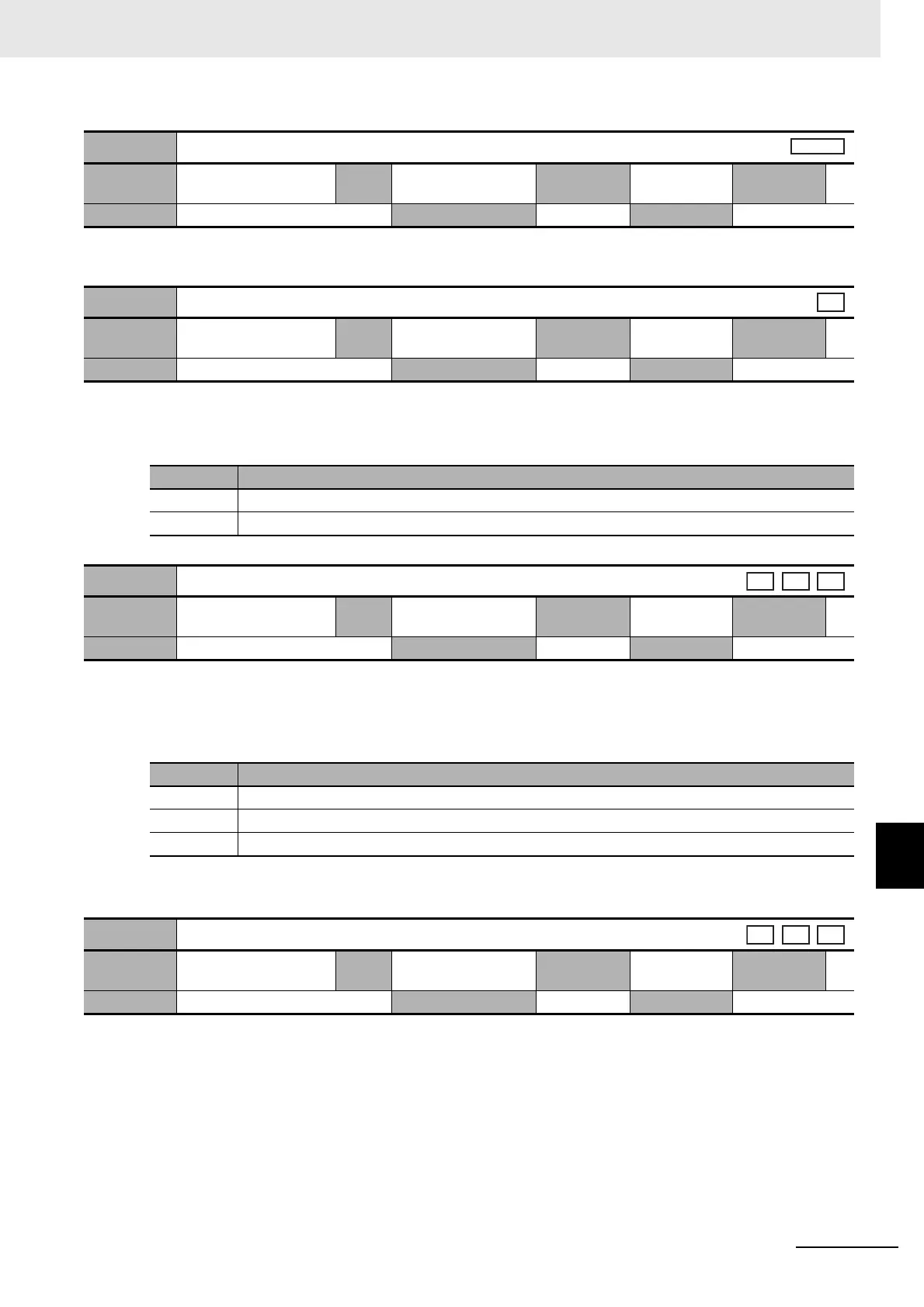
• Set the time to indicate the node address when the control power is turned ON.
• Set the condition for force limiting signal during force control.
Explanation of Settings
• Select to enable or disable the backlash compensation during position control. Set the compensation
direction when compensation is enabled.
Explanation of Settings
For details, refer to 7-4 Backlash Compensation on page 7-13.
• Set the backlash compensation amount during position control.
For details, refer to 7-4 Backlash Compensation on page 7-13.
3701 hex
Power ON Address Display Duration Setting
Setting
range
0 to 1,000
Unit
100 ms
Default
setting
0 Data
attribute
R
Size 2 bytes (INT16) Access RW PDO map Not possible
3703 hex
Force Limit Flag Output Setting
Setting
range
0 to 1
Unit
–
Default
setting
1 Data
attribute
A
Size 2 bytes (INT16) Access RW PDO map Not possible
Set value Description
0 Turn ON at force limits including the force command value.
1 Turn ON at force limits excluding the force command value.
3704 hex
Backlash Compensation Selection
Setting
range
0 to 2
Unit
–
Default
setting
0 Data
attribute
C
Size 2 bytes (INT16) Access RW PDO map Not possible
Set value Description
0 Disable backlash compensation.
1 Compensate for backlash at the first positive movement after the servo turns ON.
2 Compensate for backlash at the first negative movement after the servo turns ON.
3705 hex
Backlash Compensation Amount
Setting
range
–32,768 to 32,767
Unit
Command unit
Default
setting
0 Data
attribute
B
Size 2 bytes (INT16) Access RW PDO map Not possible
cst
csp
pp
hm
csp
pp
hm
 Loading...
