7 Using the I/O signal functions
S8BA-24D24D□□□LF
7-1-3 I/O signal port (RJ45 connector)
Outlook of the connector
Pin
Item
Backup signal output (BU)
Trouble signal output (TR)
Battery LOW signal output (BL)
Backup stop signal input (BS)
Battery Replacement Signal output (WB)
7-1-4 Contact signal ratings
Signal output (BL, TR, BU, WB) ▪Photo coupler ratings
▪Applicable voltage: DC50V or less
Remote ON/OFF input ▪Voltage between terminals: DC5V
▪Current when closed: 10mA max.
UPS Stop Signal input (BS) ▪Input voltage: HIGH(ON) DC 8 to 24 V
LOW(OFF) DC0.5V or less
▪Input current: 1.7 to 5.1mA
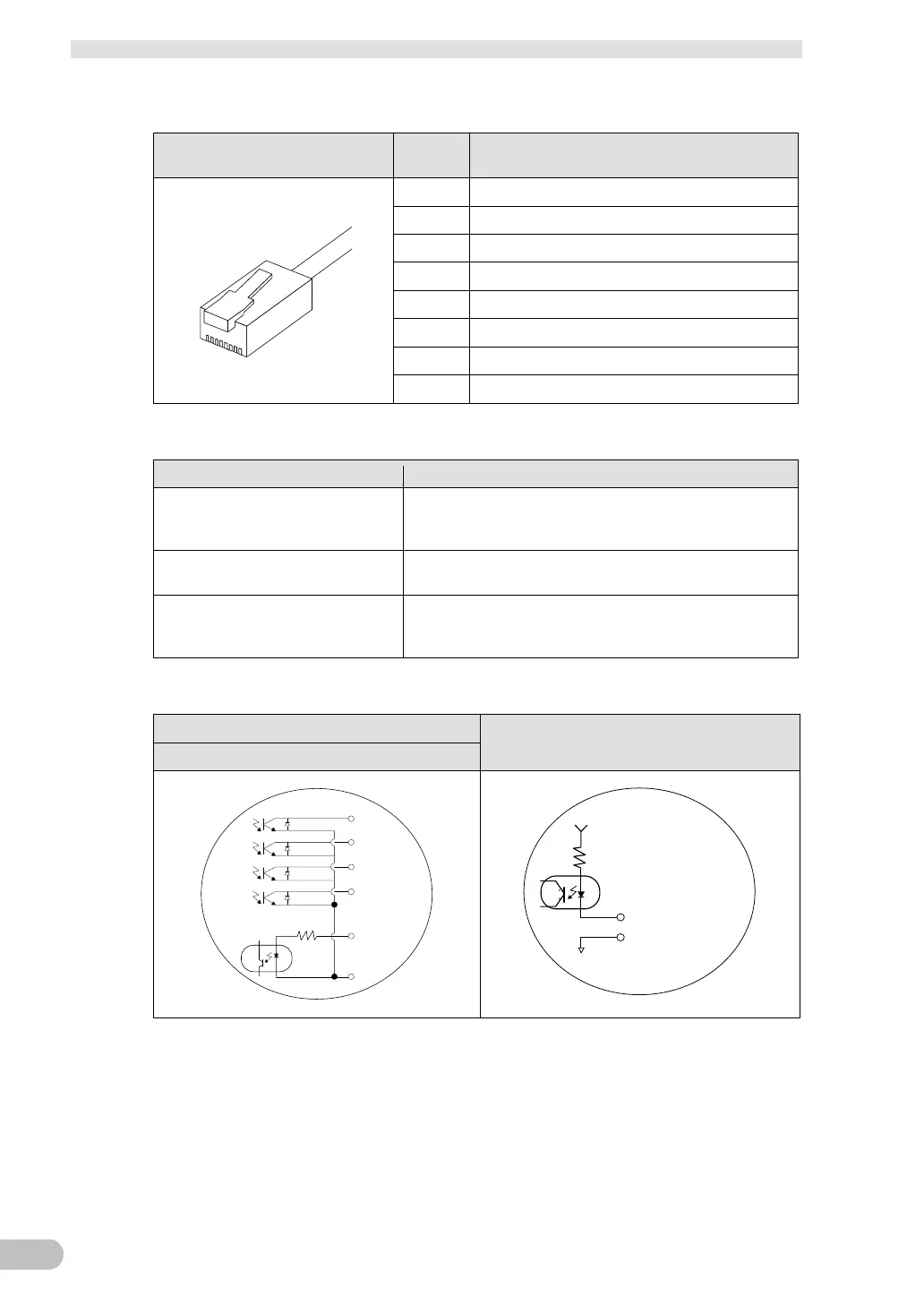
7-1-5 Contact signal circuit
Signal output (BL, TR, BU, WB)
Remote ON/OFF input
UPS Stop Signal input (BS)
5V
680Ω
Remote ON/OFF (+)
Remote ON/OFF (-)
 Loading...


