4-3SectionMaximum Current and Power Supplied
35
In addition, when PC Link Units are used, a maximum of ten Special I/O Units
and
PC Link Units total can be mounted
to one Expanded PC. When a High-den
-
sity
I/O Unit is mounted to a Remote I/O Slave Rack, the RM001-PV1 or RM201
Remote I/O Master Unit must be used.
4-3 Maximum Current and Power Supplied
The
power supplies, including those built in the CPUs, are limited in the total cur
-
rent they can supply to I/O units.
The
table below shows the maximum currents supplied by each power supply
.
There are three categories in the “Maximum current supplied”:
1, 2, 3...
1. The
5-V internal logic current powers I/O Cards and communications cards.
Refer to the deductions table to determine what trade-offs must be made
when the total I/O and peripherals exceed the CPUs internal logic current
capacity.
2. The 26-V relay current powers relay output cards and ID Sensor Units.
3. Finally,
the external 24-VDC power supply on the CPU powers external
in
-
put devices.
The
total wattage of all three categories cannot exceed the wattage
listed in the
last column, “Maximum power”.
You should not exceed any of the individual current ratings for the voltage
supplied
by any single unit, nor should you exceed the total maximum power out
-
put.
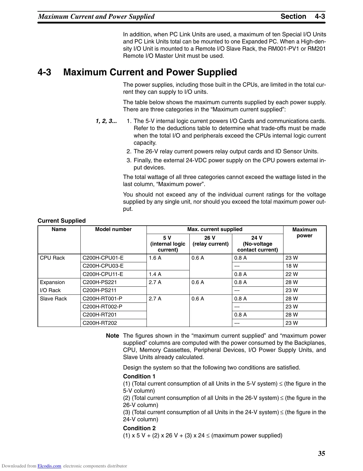
Current Supplied
Name Model number Max. current supplied
Maximum
5 V
(internal logic
current)
26 V
(relay current)
24 V
(No-voltage
contact current)
power
CPU Rack C200H-CPU01-E 1.6 A 0.6 A 0.8 A 23 W
C200H-CPU03-E --- 18 W
C200H-CPU11-E 1.4 A 0.8 A 22 W
Expansion C200H-PS221 2.7 A 0.6 A 0.8 A 28 W
I/O Rack C200H-PS211 --- 23 W
Slave Rack C200H-RT001-P 2.7 A 0.6 A 0.8 A 28 W
C200H-RT002-P --- 23 W
C200H-RT201 0.8 A 28 W
C200H-RT202 --- 23 W
Note The figures shown in the “maximum current supplied” and “maximum power
supplied”
columns
are computed with the power consumed by the Backplanes,
CPU, Memory Cassettes, Peripheral Devices, I/O Power Supply Units, and
Slave Units already calculated.
Design the system so that the following two conditions are satisfied.
Condition 1
(1)
(T
otal current consumption of all Units in the 5-V system)
≤
(the figure in the
5-V column)
(2)
(T
otal current consumption of all Units in the 26-V system)
≤
(the figure in the
26-V column)
(3)
(T
otal current consumption of all Units in the 24-V system)
≤
(the figure in the
24-V column)
Condition 2
(1) x 5 V + (2) x 26 V + (3) x 24 ≤ (maximum power supplied)
Downloaded from Elcodis.com electronic components distributor

 Loading...