7-2SectionWiring
56
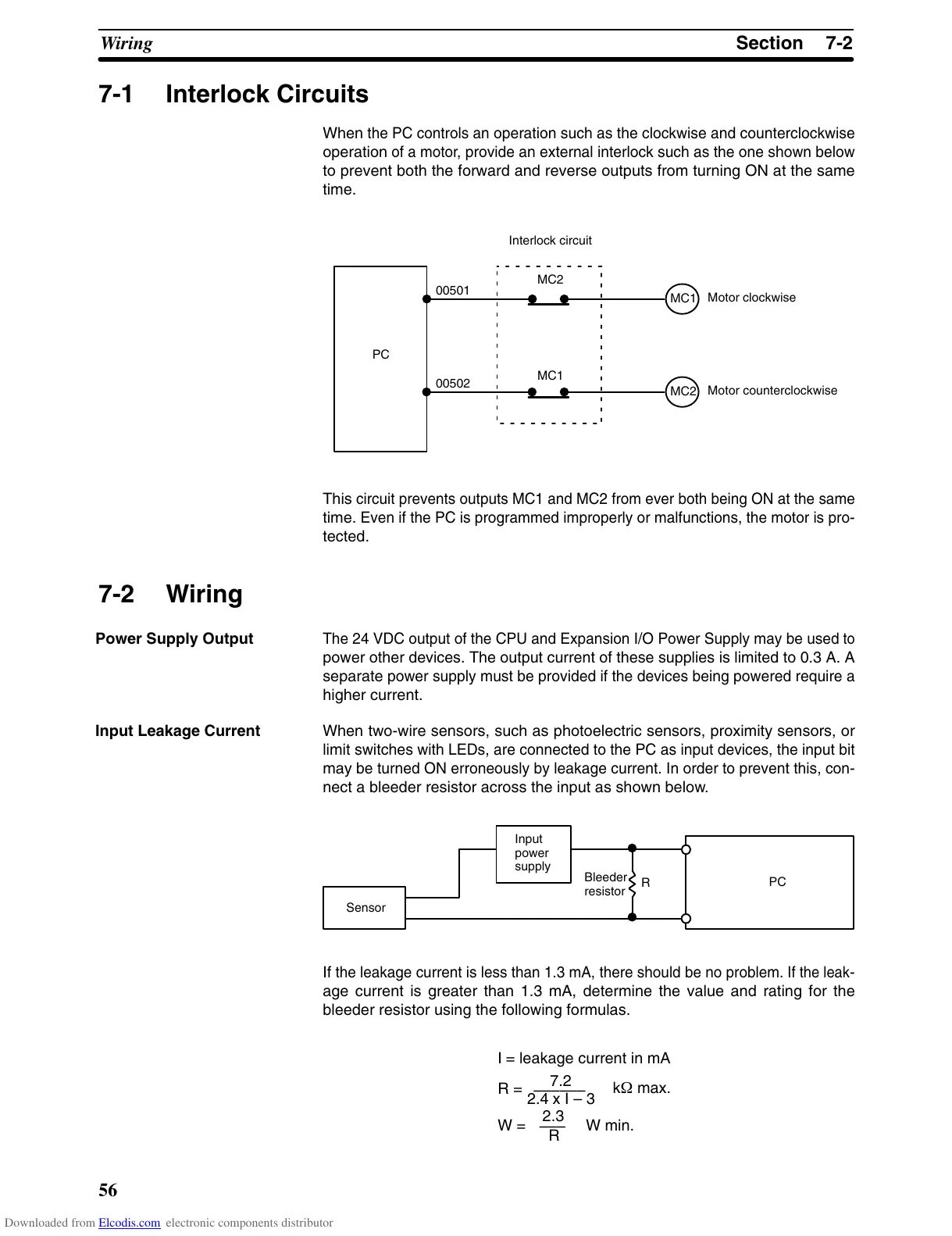
7-1 Interlock Circuits
When
the PC controls an
operation such as the clockwise and counterclockwise
operation
of a motor
, provide an external interlock such as the one shown below
to prevent both the forward and reverse outputs from turning ON at the same
time.
PC
MC2
MC1
00501
00502
MC1
MC2
Motor clockwise
Motor counterclockwise
Interlock circuit
This
circuit prevents outputs MC1 and MC2 from ever both being ON at the same
time.
Even if the PC is programmed improperly or malfunctions, the motor is pro
-
tected.
7-2 Wiring
The 24 VDC output of the CPU and Expansion I/O Power Supply may be
used
to
power
other devices. The output current of these supplies is limited to 0.3 A. A
separate
power supply must be provided if the devices being powered require a
higher current.
When two-wire sensors, such as photoelectric sensors, proximity sensors, or
limit
switches
with LEDs, are connected to the PC as input devices, the input bit
may
be turned ON erroneously by leakage current. In order to prevent this, con
-
nect a bleeder resistor across the input as shown below.
Sensor
Input
power
supply
Bleeder
resistor
R
PC
If
the leakage current is less than 1.3 mA, there should be no problem.
If the leak
-
age current is greater than 1.3 mA, determine the value and rating for the
bleeder resistor using the following formulas.
7.2
2.4 x I – 3
––––––
R =
kW max.
W =
2.3
R
–––
W min.
I = leakage current in mA
Power Supply Output
Input Leakage Current
Downloaded from Elcodis.com electronic components distributor

 Loading...