DASHPOT
GOVERNOR
ARM BRACKET
0.050
INCH
(1.27
mm)
FIGURE
7.
DASHPOT
CLEARANCE
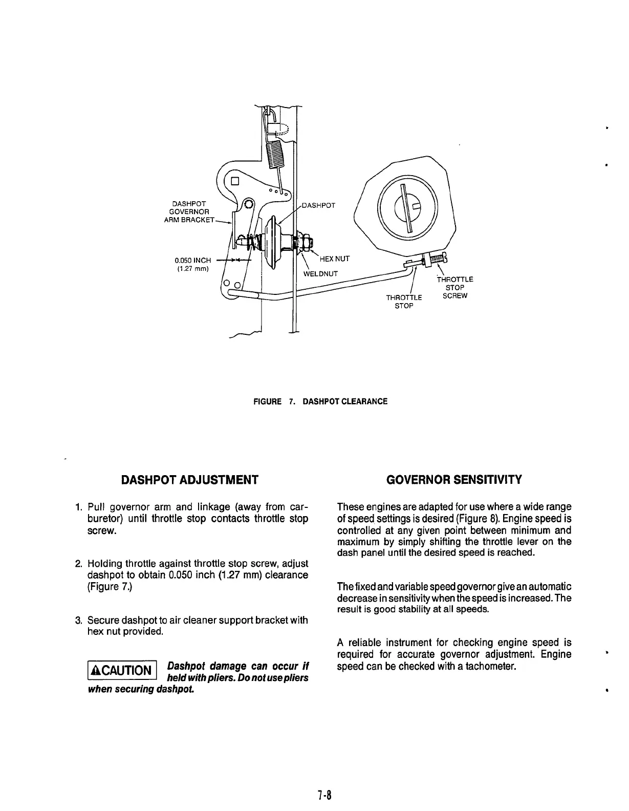
DASHPOT ADJUSTMENT
1.
Pull governor arm and linkage (away from car-
buretor) until throttle stop contacts throttle stop
screw.
2.
Holding throttle against throttle stop screw, adjust
dashpot to obtain
0.050
inch
(1.27
mm) clearance
(Figure
7.)
3.
Secure dashpot to air cleaner support bracket with
hex nut provided.
ACAUT~ON
Dashpot
damage can occur
if
a
held
with
pliers.
Do
not use
p/iers
STOP
GOVERNOR SENSITIVITY
These engines are adapted for use where
a
wide range
of
speed settings is desired (Figure
8).
Engine speed
is
controlled at any given point between minimum and
maximum by simply shifting the throttle lever on the
dash panel until the desired speed is reached.
The fixed and variable speed governor give an automatic
decrease in sensitivity when the speed is increased. The
result is
good
stability at
all
speeds.
A
reliable instrument for checking engine speed is
required
for
accurate governor adjustment. Engine
speed can be checked with a tachometer.
when securing dashpot.
7
-8
Redistribution or publication of this document,
by any means, is strictly prohibited.
 Loading...
