2.
Assemble brushes
so
that the chamfered side is
away from the brush springs. Make sure brush
wires
do
not rub against the commutator or end cap.
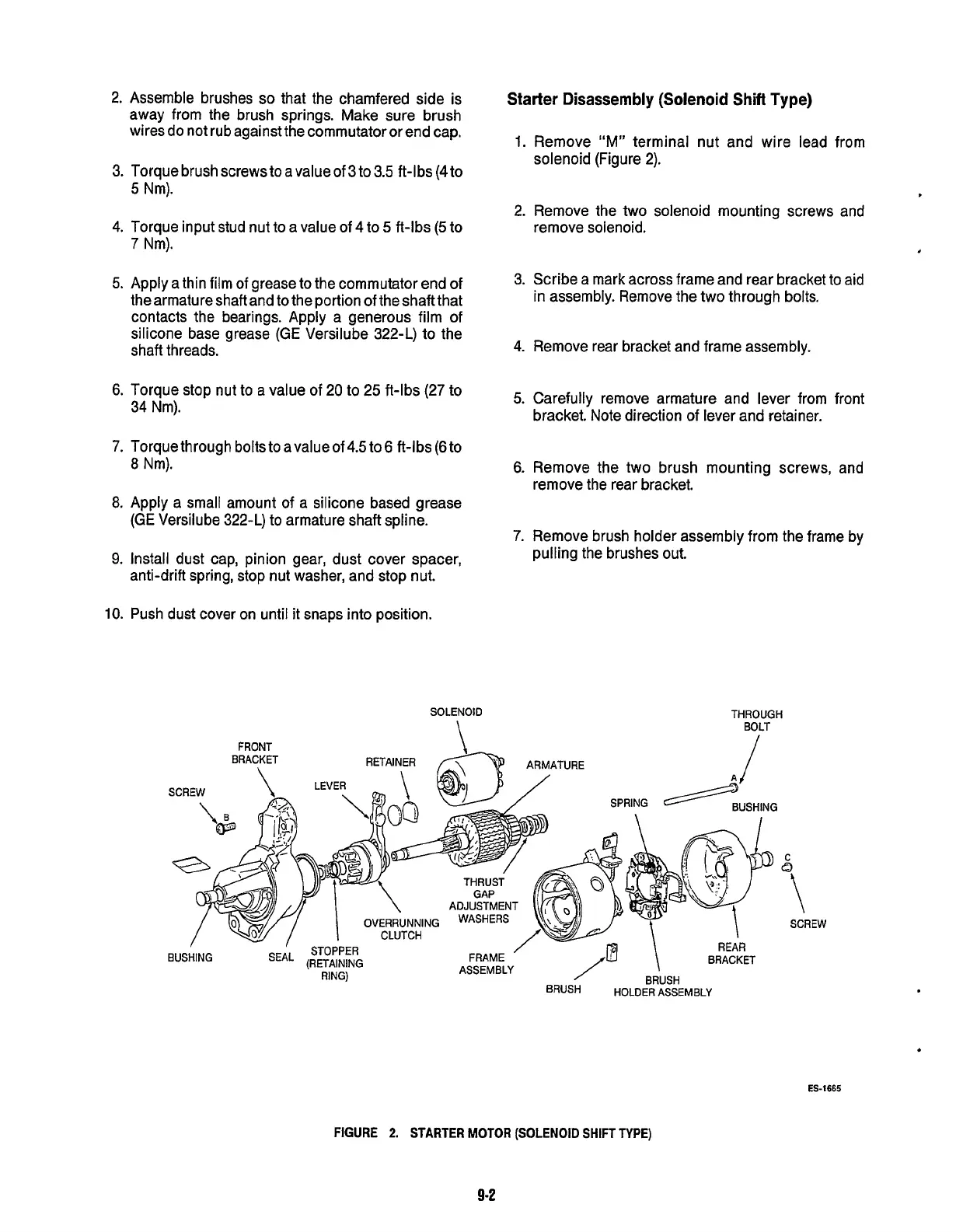
Starter
Disassembly (Solenoid
Shifl
Type)
1.
Remove "M" terminal nut and wire lead from
solenoid (Figure 2).
3. Torque brush screws to a value
of
3
to
3.5 ft-lbs
(4tO
5
Nm).
2. Remove the
two
solenoid mounting screws and
remove solenoid.
4.
Torque input stud nut
to
a value of 4 to
5
ft-lbs
(5
to
7
Nm).
3. Scribe a mark across frame and rear bracket to aid
in assembly. Remove the two through bolts.
5.
Apply a thin film of grease to the commutator end of
the armature shaft and
to
the portion of the shaft that
contacts the bearings. Apply a generous film of
silicone base grease
(GE
Versilube 322-L) to the
shaft threads.
4.
Remove rear bracket and frame assembly.
6.
Torque stop nut
to
a
value of 20
to
25
ft-lbs
(27
to
34 Nm).
5.
Carefully remove armature and lever from front
bracket. Note direction of lever and retainer.
7.
Torque through bolts to avalueof
4.5
to
6
ft-lbs
(6
to
8
Nm).
6.
Remove the two brush mounting screws, and
remove the rear bracket.
8.
Apply a small amount of a silicone based grease
(GE
Versilube 322-L) to armature shaft spline.
7.
Remove brush holder assembly from the frame by
pulling the brushes out.
9.
Install dust cap, pinion gear, dust cover spacer,
anti-drift spring, stop nut washer, and stop nut.
10.
Push dust cover on until
it
snaps into position.
SOLENOID
\
THROUGH
BOLT
FRONT
/
BRACKET
RETAINFR
SCREW
\
LEVEF
mn
C
I
\
GAP
OVERRUNNING
WASHERS
CLUTCH
.nn"T"
-.
..
\
ADJUSTMENT
SCREW
\
RFAR
C.T
.
.
-.
..
.
BRACKET
FRAME
ASSEMBLY
31
urrcn
RING)
SEAL
(RETAINING
BUSHING
BRUSH
HOLDER
ASSEMBLY
ES-1665
FIGURE
2.
STARTER MOTOR
(SOLENOID
SHIFT TYPE)
9-2
Redistribution or publication of this document,
by any means, is strictly prohibited.
 Loading...
