Ignition
and
Battery
Charging
I
G
N
IT1
0
N
SYSTEM
D
ESCRl PTI
ON
The engine is equipped with an automotive type battery
ignition system. Both spark plugs fire simultaneously,
thus
the need for
a
distributor
is
eliminated.
I
IGNITION
TIMING
Thetiming is preset at thefactory. Slight timing changes
can be made by adjusting the point gap.
BREAKER
POINTS
The timing is adjusted
to
specification during initial
engine assembly and is fixed by the point gap adjust-
ment.
To
maintain maximum engine efficiency, change
the breaker points as recommended in the Periodic
Maintenance Schedule.
Replacement and Adjustment
1.
Remove spark plugs.
2.
Remove breaker box cover. Rotatecrankshaftclock-
wise (facing flywheel) until points are fully open.
3.
Remove condenser (screw A) and detach condenser
lead and coil lead (screw
6).
Engines with con-
densers mounted on the air cleaner bracket
do
not
need
to
be removed unless being replaced.
4.
Remove two Allen screws (C) and lift breaker
assembly from engine.
5.
Replace condenser and point assembly with new
parts and reinstall using above procedure in reverse
order of removal.
6.
Adjust point gap by rotating crankshaft clockwise
(facing flywheel) by hand until the points are fully
open. Set the point gap (using flat feeler gauge)
to
gap specified in
Sf€ClFlCATlONS
by adjusting the
Allen screw (D) inward or outward (Figure
1).
A.016
point gap is equivalent to 16" BTC.A.020 inch point
gap is equivalent to 20" BTC. Make sure feeler
gauge
is
clean and free
of
any grease, oil, or dirt.
POINTGAP
,.
W
FIGURE
1.
SETTING
POINT
GAP
7.
Replace breaker box cover, coil wire, spark plugs,
and spark plug cables.
Timing Test
As a check for proper ignition timing
a
continuity test
may be performed:
1.
Adjust breaker points.
2.
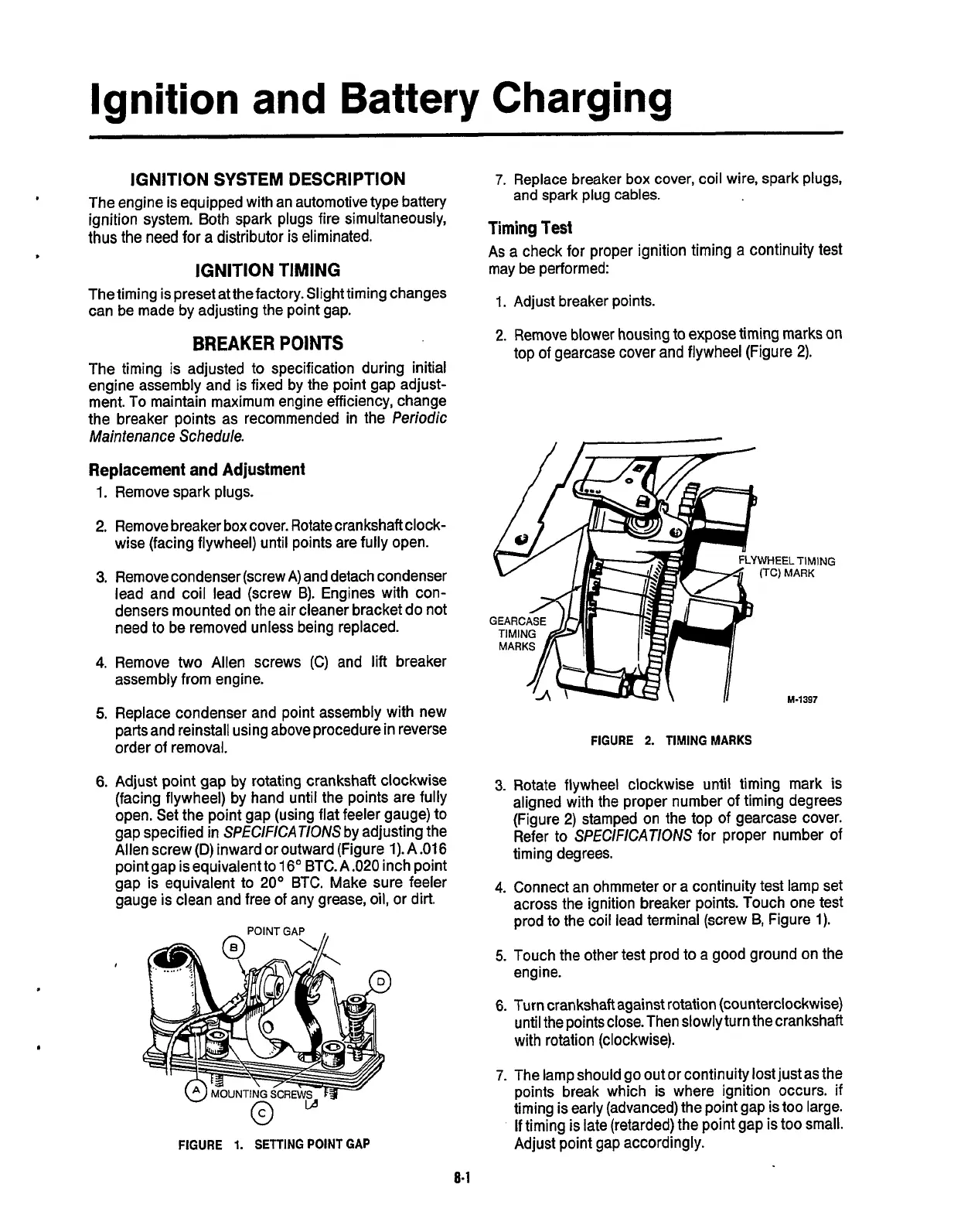
Remove blower housing
to
expose timing marks on
top
of
gearcase cover and flywheel (Figure
2).
YWHEELTIMING
(TC)
MARK
M-1397
FIGURE
2.
TIMING
MARKS
3.
Rotate flywheel clockwise until timing mark
is
aligned with the proper number of timing degrees
(Figure
2)
stamped on the top of gearcase cover.
Refer to
SPEClFlCATlONS
for proper number
of
timing degrees.
4.
Connect an ohmmeter or a continuity test lamp set
across the ignition breaker points. Touch one test
prod to the coil lead terminal (screw
B,
Figure
1).
5.
Touch the other test prod to a good ground on the
engine.
6.
Turn crankshaft against rotation (counterclockwise)
until the points close. Then slowly turn the crankshaft
with rotation (clockwise).
7.
The lamp should go out or continuity lost just as the
points break which is where ignition occurs.
if
timing is early (advanced) the point gap is
too
large.
If
timing is late (retarded) the point gap is
too
small.
Adjust point gap accordingly.
Redistribution or publication of this document,
by any means, is strictly prohibited.
 Loading...
