2.
The regulator-rectifier has built in protection against
open circuits or short circuits on the alternator
output (B+) terminal. Either condition will cause the
regulator-rectifier toshut
off
and appear as
if
it is not
functioning. Prior to checking theregulator-rectifier,
check all wiring between the regulator-rectifier
B+
terminal and the battery positive
(+)
terminal to
assure it is free of open circuits, resistances or short
circuits. Also, if the battery is extremely discharged
it may have insufficient power to “turn on” the
regulator-rectifier.
3.
Be sure regulator-rectifier plug (connector) is
inserted properly. Plug must bottom in receptacle;
this eliminates any resistance due to a poor
connection. Keep clean and tight.
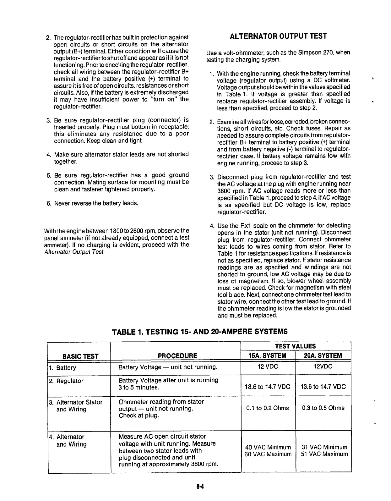
BASIC
TEST
1. Battery
4.
Make sure alternator stator leads are not shorted
together.
5.
Be sure regulator-rectifier has a good ground
connection. Mating surface for mounting must be
clean and fastener tightened properly.
6. Never reverse the battery leads.
PROCEDURE
15A.
SYSTEM
Battery Voltage
-
unit not running.
12
VDC
With the engine between
1800
to 2600 rpm, observe the
panel ammeter (if not already equipped, connect a test
ammeter).
If
no charging is evident, proceed with the
Alternator Output Test.
2.
Regulator
ALTERNATOR
OUTPUT
TEST
Battery Voltage after unit is running
3
to
5
minutes.
13.6 to
14.7
VDC
Use a volt-ohmmeter, such as the Simpson
270,
when
testing the charging system.
3.
Alternator Stator
.
and Wiring
1.
With the engine running, check the battery terminal
voltage (regulator output) using a DC voltmeter.
Voltage output should be within the values specified
in Table
1.
If voltage is greater than specified
replace regulator-rectifier assembly.
If
voltage is
less than specified, proceed to step 2.
I
*
Ohmmeter reading from stator
output
-
unit not running.
Check at plug.
0.1
to
0.2
Ohms
2.
Examineall wiresfor loose, corroded, broken connec-
tions, short circuits, etc. Check fuses. Repair as
needed to assure complete circuits from regulator-
rectifier B+ terminal
to
battery positive
(+)
terminal
and from battery negative
(-)
terminal to regulator-
rectifier case.
If
battery voltage remains low with
engine running, proceed to step 3.
3.
Disconnect plug from regulator-rectifier and test
the AC voltage at the plug with engine running near
3600 rpm.
If
AC voltage reads more or less than
specified in Table
1,
proceed to step
4.
If
AC voltage
is as specified but DC voltage is low, replace
regulator-rectifier.
4.
Use the
Rxl
scale on the ohmmeter for detecting
opens in the stator (unit not running). Disconnect
plug from regulator-rectifier. Connect ohmmeter
test leads to wires coming from stator. Refer to
Table
1
for resistance specifications.
If
resistance is
not as specified, replace stator.
If
stator resistance
readings are as specified and windings are not
shorted to ground, low AC voltage may be due to
loss
of magnetism.
If
so,
blower wheel assembly
must be replaced. Check for magnetism with steel
tool blade. Next, connect one ohmmeter test lead to
stator wire, connect the other test lead to ground.
If
the ohmmeter reading is low the stator is grounded
and must be replaced.
TABLE
1.
TESTING
15- AND
PO-AMPERE SYSTEMS
I
I
TEST
‘
(4.
Alternator
and Wiring
Measure
AC
open
circuit stator
voltage with unit running. Measure
between two stator leads with
plug disconnected and unit
running at approximately
3600
rprn.
I
40
VAC Minimum
60 VAC Maximum
rLUES
20A.
SYSTEM
12VDC
13.6
to
14.7
VDC
0.3
to
0.5
Ohms
31 VAC Minimum
51
VAC Maximum
.
8-4
Redistribution or publication of this document,
by any means, is strictly prohibited.
 Loading...
