Section
5.
Cooling
System
GENERAL
Throughout this manual, flotation water drawn into the
boat for engine cooling iscalled sea water. Water recircu-
lated through the engine closed system is called captive
water. Thus, confusion is avoided with other generic
terms describing water use.
The
two
types of marine cooling systems covered in this
manual are
heat exchanger
and
sea wafer
cooling. An
explanation
of
each system, and the advantages and
disadvantages of each are covered in separate chapter
headings. The heat exchanger system is ordered most
often and is standard on the
MCE
generator set Sea
water cooling is an available option.
System
Plumbing
To adequately cool the generator set under all conditions,
the plumbing system must be properly planned and
installed. Excess lengths of plumbing increases flow
resistance and results in reduced cooling. An air leak in
the sea water intake will reduce cooling, cause corrosion,
and can even destroy the neoprene impeller in the
sea
water pump. The neoprene impeller must never be run
dry, and should be primed before initial start
The water line should have a minimum inside diameter of
0.75
inch
(1
9
mm). For runs over
20
feet
(5.2
m), increase
the line one pipe size for each additional
10
feet
(2.6
m) of
length. Water lines can be either copper tubing or flexible
hose. Be sure a length of flexible hose is used at the
generator set connection to allow set movement and for
noise abatement
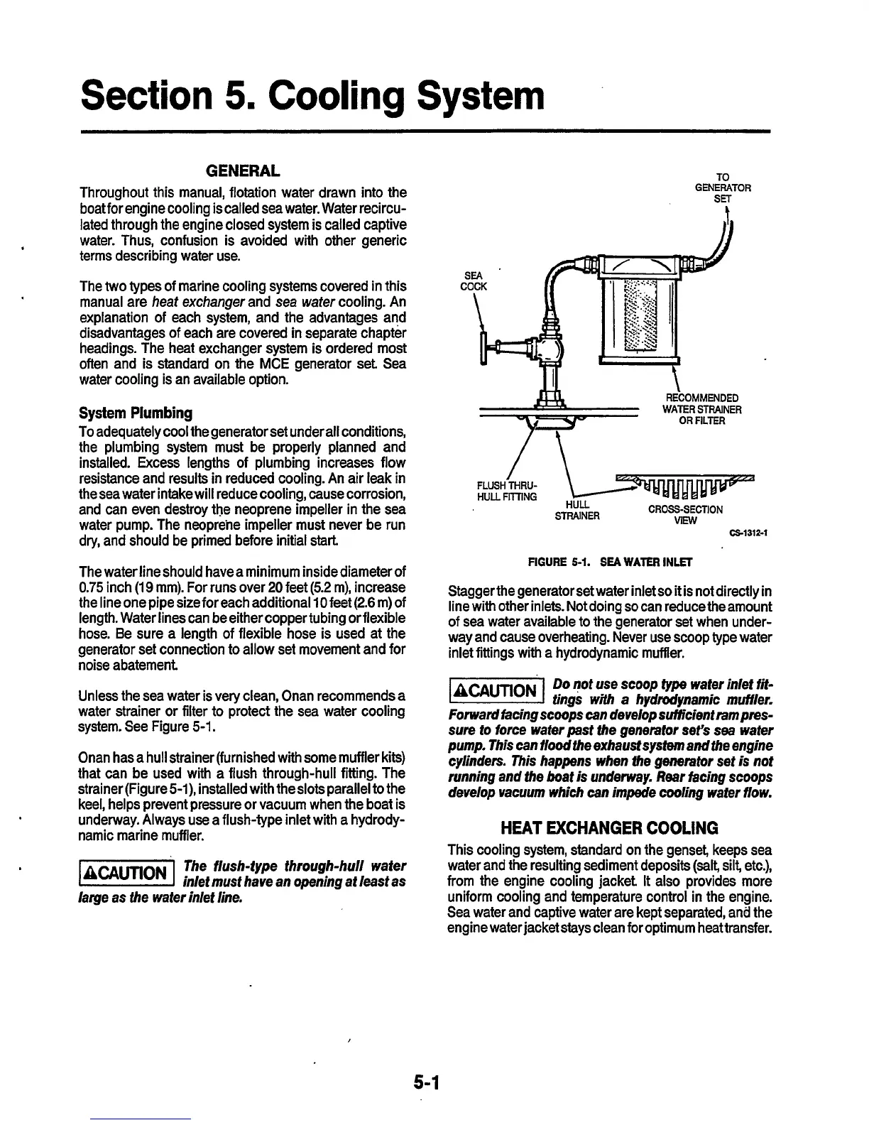
Unless the sea water is very clean, Onan recommends a
water strainer or filter to protect the sea water cooling
system. See Figure
5-1.
Onan has a hull strainer (furnished with some muffler kits)
that can be used with a flush through-hull fitting. The
strainer (Figure
!SI),
installed with theslots parallel to the
keel, helps prevent pressure or vacuum when the boat is
underway. Always use a flush-type inlet with a hydrody-
namic marine muffler.
The flush-fype through-hull wafer
inlef must have
an
opening at least as
lame as fhe wafer inlef line.
TO
GENERATOR
SET
RECOMMENDED
WATER
STRAINER
OR
FILTER
FLUSH
THRU-
HULL
FllllNG
STF
CROSS-SECTION
VlMl
HULL.
--WNER
CS-1312-1
FIGURE
5-1.
SEA
WATER
INLET
Stagger the generator set water inlet
so
it is not directly in
line with other inlets. Not doing
so
can reduce the amount
of sea water available to the generator set when under-
way and cause overheating. Never use scoop type water
inlet fittings with a hydrodynamic muffler.
-1
Do
not use scoop
fype
wafer inlet
fit-
tings with
a
hydrodynamic muifler.
Forward
facing
scoops can develop suiiicienf
rampres-
sure
to force wafer
past
the
generator
sefs
sea
wafer
pump. This can floodfhe exhausfsystemandfhe engine
cylinders. This
happens
when the generator set
is
not
running and the boat
is
underway.
Rear
iacing scoops
develop vacuum which can impede
ding
wafer flow.
HEAT EXCHANGER COOLING
This cooling system, standard on the genset, keeps sea
water and the resulting sediment deposits
(salt,
silt, etc.),
from the engine cooling jacket It also provides more
uniform cooling and temperature control in the engine.
Sea water and captive water are kept separated, and the
engine water jacket stays clean for optimum heat transfer.
5-1
 Loading...


