Exhaust
Cooling
Water
Injection
The neoprene impeller pump moves the
sea
water
through the
cooling
system and into the exhaust manifold.
The injected water cools the exhaust and prevents
exhaust system damage from heat
A
temperature oper-
ated switch on theexhaust manifold shu tsthe unit down if
overheating occurs. The switch closes if temperature
reaches
175'
to
185°F
(79'
to
85'C)
and actuates the
Fault Reset breaker on the control panel.
If
high exhaust
temperature shutdown occurs, the entire exhaust system
should be checked for any signs
of
overheating, espe-
cially the exhaust hoses. Replace defective components
immediately, and do not operate the generator set until
Inhalation of exhaust gas
can
cause
jawnR"Gl
severe personal
injury
or
death.
Do
not operate the generator set after a high exhaust
temperature shufdown until the entire exhaust system
has been checked
and
serviced as mquimd.
.
system is repaired.
DO
NOT
USE
SCOOP
TYPE
WATER
-1
INLET FITTINGS. Forward
facing
scoops
can
develop suificient ram
pressure
to
torce
wafer
past
the
generator set's
sea
waferpump. Thiscan
flood
the
exhaust system and the engine cylinders. This
happens when the generafor set
is
not running and the
boat
is
underway. Rear facing scoops develop vacuum
which
can
impede
cooling
water flow.
BELOW
LOAD
WATERLINE
INSTALLATION
Figure
6-1
shows details
of
a
recommended below load
waterline installation. Review and apply
data
from
the
preceding
G€N€ML
section, plus the following.
Siphon
Break
Install a siphon break (anti-siphon)
if
the
sea
water injec-
tion port on
the
exhaust manifold
is
at or below
the
load
waterline. The siphon break is a vacuum operated vent
valve that opens the exhaust water discharge line to the
atmosphere when the engine
is
not operating. The open
vent valve prevents
sea
water (flotation water) from being
siphoned into the exhaust manifold and cylinders on
engines installed below load waterline.
The siphon break hoses connect between the exhaust
manifold water injection port and the water tube from the
heat exchanger. Connect the siphon break hose ends to
these connectors. Remove plug from top panel and route
hoses through the hole.
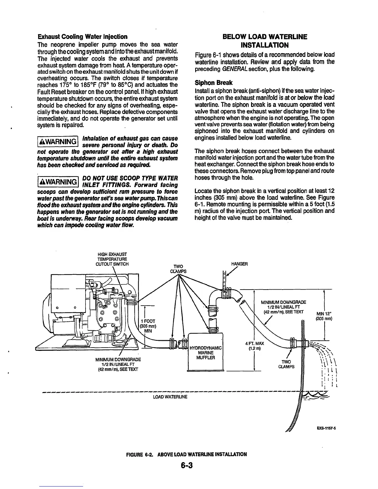
Locate the siphon break in a vertical position at least
12
inches
(305
mm) above the load waterline.
See
Figure
6-1.
Remote mounting is permissible within a
5
foot
(1.5
m) radius
of
the injection port The vertical position and
height of the valve must be maintained.
HIGH EXHAUST
TEMPERATURE
CUTOUT,SWITCH
TWO
HANGER
MINIMUM
DOWNGRADE
112
INlLlNEAL
FT
-------------------------------------------------------
LOAD WATERLINE
FIGURE
6-2.
ABOVE
LOAD
WATERLINE
INSTALIATION
6-3
 Loading...


