REMOTE STARTING CONTROLS
Onan has control panel kits available for remotestarting
and stopping of the genset The kits vary from a basic
single-pole, double-throw, momentary-on switch on up
to remote-gauge controls with running time meter, bat-
tery condition meter, and engine monitors. The kits
come with installation instructions and wiring diagrams
for connection.
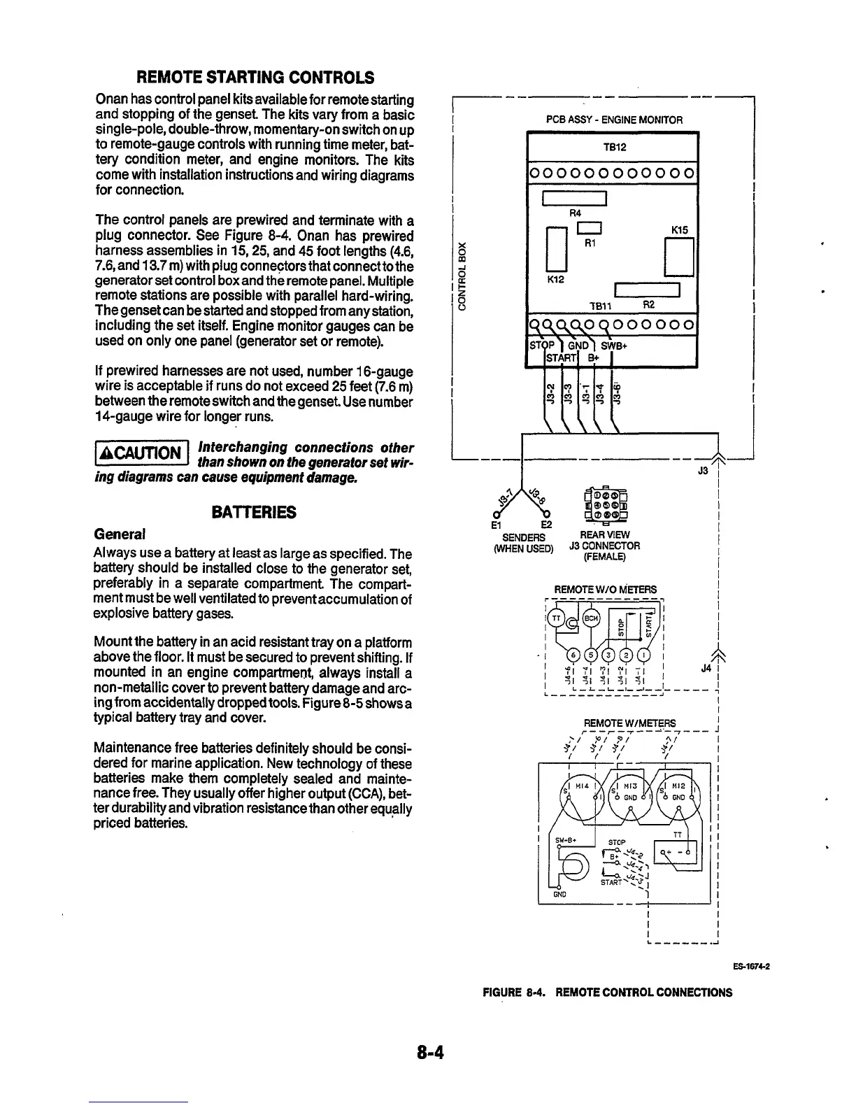
The control panels are prewired and terminate with a
plug connector. See Figure 8-4. Onan has prewired
harness assemblies in
15,25,
and 45 foot lengths (4.6,
7.6,
and
13.7
m) with plug connectors that connect to the
generator set control boxand the remote panel. Multiple
remote stations are possible with parallel hard-wiring.
The genset can be started and stopped from any station,
including the set itself. Engine monitor gauges can be
used on only one panel (generator set or remote).
If prewired harnesses are not used, number 16-gauge
wire is acceptable if runs do not exceed
25
feet (7.6 m)
between the remote switch and the genset. Use number
14-gauge wire for longer runs.
-1
lnterchanging connections other
ihan shown on the generator set wir-
ing
diagrams can cause equipment damage.
BATTERIES
General
Always use a battery at least as large as specified. The
battery should be installed close to the generator set,
preferably in a separate compartment The compart-
ment must be well ventilated to preventaccumulation of
explosive battery gases.
Mount the battery in an acid resistant tray on a platform
above the floor. It must be secured to prevent shifting. If
mounted in an engine compartment, always install a
non-metallic cover to prevent battery damage and arc-
ing from accidentally dropped tools. Figure 8-5 shows a
typical battery tray and cover.
Maintenance free batteries definitely should be consi-
dered for marine application. New technology of these
batteries make them completely sealed and mainte-
nance free. They usually offer higher output
(CCA),
bet-
ter durability and vibration resistance than other equally
priced batteries.
PCB
ASSY
-
ENGINE
MONITOR
I
TB12
I
11"
K12
n
0
GND
1
ES-167c2
FIGURE
8-4.
REMOTE
CONTROL CONNECTIONS
 Loading...


