SEA WATER
COOLING
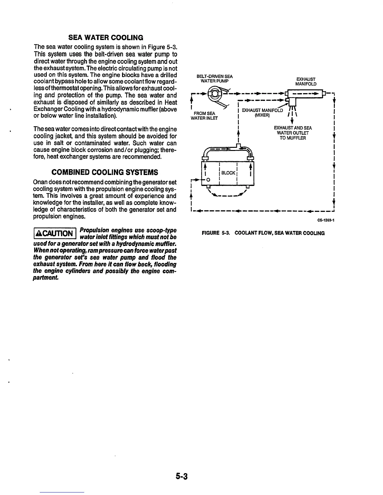
The sea water cooling system is shown in Figure
5-3.
This
system
uses
the belt-driven
sea
water pump to
direct water through the engine cooling system and out
the exhaust system. The electric circulating pump
is
not
used on this system. The engine blocks have a drilled
coolant bypass hole to allow some coolantflow regard-
less of thermostat opening. This allows for exhaust cool-
ing and protection of the pump. The sea water and
exhaust is disposed
of
similarly as described in Heat
Exchanger Cooling with a hydrodynamic muffler (above
or
below water line installation).
The sea water comes into direct contact with the engine
cooling jacket, and this system should be avoided for
use
in salt
or
contaminated water. Such water can
cause engine block corrosion and/or plugging; there-
fore, heat exchanger systems are recommended.
.
COMBINED
COOLING
SYSTEMS
Onan does not recommend combining the generator set
cooling system with the propulsion engine cooling sys-
tem. This involves a great amount of experience and
knowledge for the installer, as well as complete know-
ledge
of
characteristics of both the generator set and
propulsion engines.
Propulsion engines use scoop-type
water inlet fittings which must not be
used for a generator set with a hydrodynamic muffler.
When not operating, ram pressure can force waferpast
the generator set’s sea water pump and flood the
exhaust system. From here it can flow back, flooding
the engine cylinders and possibly the engine com-
partment.
BELT-DRIVEN
SEA
WATER
PUMP
EXHAUST
MANIFOU)
I
,-
I
EXHAUSTMANIFOLD
/I\
FROM
SEA
I
(MIXER)
/I\
+
WATER
INLET
I
re
I
EXHAUST AND
SEA
WATER OUTLET
TO
MUFFLER
I
I
+
I
I
I
FIGURE
5-3.
COOLANT
FLOW.
SEA
WATER
COOLING
5-3