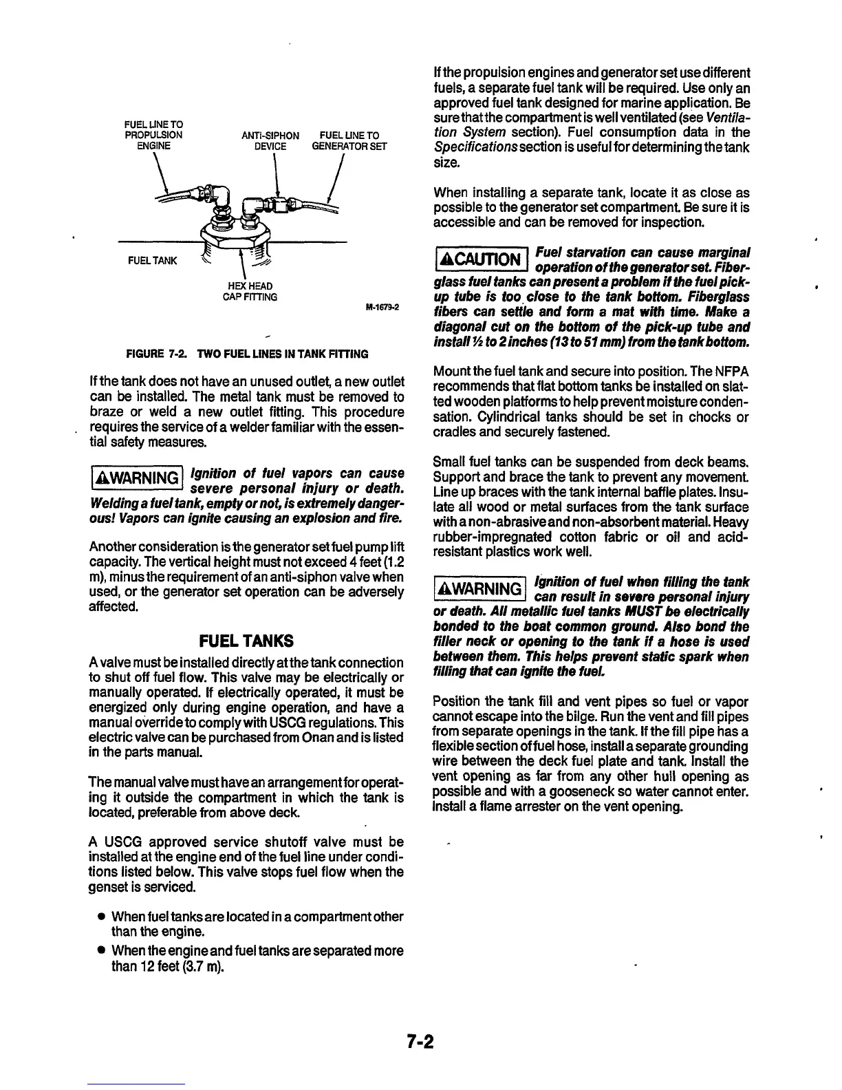
FUEL LINE TO
PROPULSION ANTI-SIPHON FUEL UNE TO
ENGINE DEVICE GENERATOR
SET
HEX
HEAD
CAP
FTTTING
FIGURE
7-2.
TWO
FUEL LINES IN
TANK
FllllNG
1-1679.2
If
the tank does not have an unused outlet, a new outlet
can be installed. The metal tank must be removed to
braze
or
weld a new outlet fitting. This procedure
.
requires the service of a welder familiar with the essen-
tial safety measures.
1-1
Ignition
of
fuel vapors can cause
severe personal injury
or
death.
Welding a
fuel
tank, empty
or
not, is extremely danger-
ous!
Vapors can ignite causing an explosion and fire.
Another consideration is the generator set fuel pump
lift
capacity. The vertical height must not exceed
4
feet
(1.2
m), minus the requirement
of
an anti-siphon valve when
used,
or
the generator set operation can be adversely
affected.
FUEL
TANKS
Avalve must be installed directly at the tank connection
to shut
off
fuel flow. This valve may be electrically
or
manually operated. If electrical1,y operated, it must be
energized only during engine operation, and have a
manual override to comply with
USCG
regulations. This
electric valve can be purchased from Onan and is listed
in the parts manual.
The manual valve must have an arrangement for operat-
ing
it
outside the compartment in which the tank is
located, preferable from above deck.
A USCG approved service shutoff valve must be
installed at the engine end of the fuel line under condi-
tions listed below. This valve stops fuel flow when the
genset is serviced.
0
When fueltanksare located in a compartment other
When the engine and fuel tanks are separated more
than the engine.
than
12
feet
(3.7
m).
If the propulsion engines and generator set usedifferent
fuels, a separate fuel tank will be required. Use only an
approved fuel tank designed
for
marine application. Be
sure thatthe Compartment is well ventilated (see
Ventila-
tion
System
section). Fuel consumption data in the
Specificafionssection is useful for determining the tank
size.
When installing a separate tank, locate it as close as
possible to the generator set Compartment. Be sure it is
accessible and can be removed for inspection.
Fuel starvation can cause marginal
operation of the generator
set.
Fiber-
glass
fuel
tanks can present a problem if the fuel pick-
up tube is too.close
to
the tank bottom. Fiberglass
fibers can seftle and
form
a
mat
wifh
time.
Make
a
diagonal cut
on
the bottom
of
the pick-up tube and
install
35
to Pinches
(73
to
51
mm) from the fankbottom.
Mount the fuel tank and secure into position. The
NFPA
recommends that flat bottom tanks be installed on slat-
ted wooden platforms to help prevent moisture conden-
sation. Cylindrical tanks should be set in chocks
or
cradles and securely fastened.
Small fuel tanks can be suspended from deck beams.
Support and brace the tank to prevent any movement.
Line up braces with the tank internal baffle plates. Insu-
late all wood
or
metal surfaces from the tank surface
with a non-abrasiveand nonabsorbent material. Heavy
rubber-impregnated cotton fabric or oil and acid-
resistant plastics work well.
Ignition of fuel
when
filling the tank
l&lZ@l
can result in
seuere
personal injury
or
death. All metallic fuel tanks
MUST
be
electrically
bonded to
the
boat common ground. Also bond the
filler neck
or
opening
to
the tank if a hose is used
between them. This helps prevent static spark when
filling that can ignite the fuel.
Position the tank
fill
and vent pipes
so
fuel
or
vapor
cannot escape into the bilge. Run the vent and
fill
pipes
from separate openings in the tank.
If
the
fill
pipe has a
flexible section of fuel hose, install aseparate grounding
wire between the deck fuel plate and tank. Install the
vent opening as far from any other hull opening as
possible and with a gooseneck
so
water cannot enter.
Install a flame arrester on the vent opening.
7-2
 Loading...


