from the position shown, push thedistributor into
its mounting hole. If necessary, turn the rotor
slightly to align teeth of gear. If the rotor is not in
position shown, repeat the procedure, changing
the gear alignment.
4. Install distributor clamp screw. If spark plug leads
were removed from distributor cap, reinstall them
in properorder,(Figure 42).Time ignition system.
Ignition Coil: The
JC
engine uses a standard
automotive ignition coil mounted on the air shroud
near the engine access door. Inspect and tighten the
primary terminals. Inspect the secondary terminal
and clean
it
if necessary.
Test the coil either on a standard automotive tester or
by checking primary and secondary winding
resistances. Resistance from the high tension
ter-
minal to the ground
(-)
terminal should be
7,000
to
10,000
ohms: resistance between the primary ter-
minals, about
1
ohm.
A quick coil check can be made bysimplydisconnec-
ting the high tension lead between coil and distributor
at the distributor, holding the end about 1/4 inch from
bare engine metal and cranking the engine. A spark
between the lead and engine indicates the coil is
operating, although it might be weak.
No
spark
indicates that the coil, points, or control circuit to the
coil are defective. Check for voltage between the coil
negative
(-)
terminal and ground while cranking the
engine, and inspect the breaker points.
Ignition Condenser: The condenser is mounted on
the outside of the distributor, Figure 46. Refer to
JB
Battery
lgnition
section for test procedure.
Capacitance should be
.25
to .28 mfd.
MAGNETO IGNITION
(JC)
Magnetos (Wico or Fairbanks-Morse) are sometimes
supplied with JC engines. If the magneto has been
removed from the engine for any reason, it must be
retimed to the firing order of the engine (1-2-4-3) at
the time of installation. Follow the procedure below
for
i
nstal lat ion
i
nst ruct ion
s.
Align the flywheel
19-1/2
teeth before the TDC (top
dead center) mark with the pointer on thefront cover.
No.
1
piston on compression stroke.This procedure is
for both magnetos.
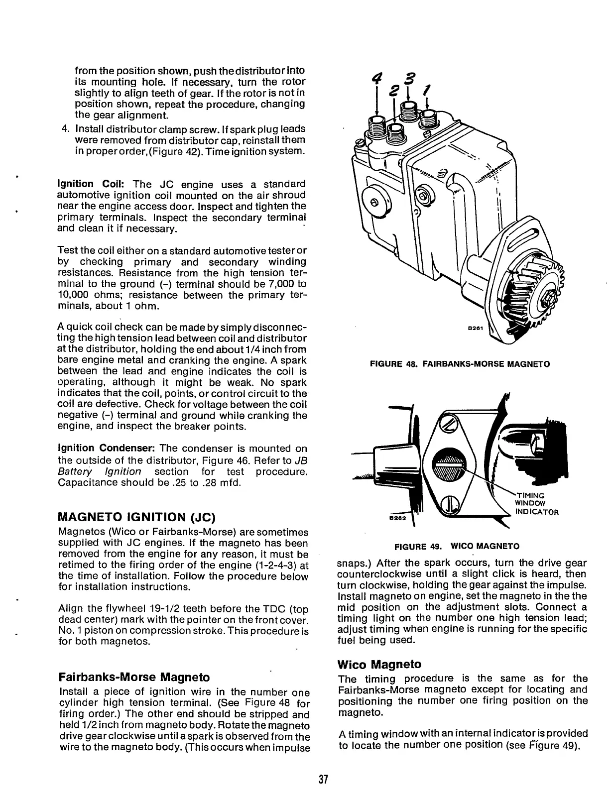
Fai rban ks-Morse Magneto
Install a piece of ignition wire in the number one
cylinder high tension terminal. (See Figure 48 for
firing order.) The other end should be stripped and
held
1/2
inch from magneto body. Rotate the magneto
drive gear clockwise until aspark is observed from the
wire to the magneto body. (This occurs when impulse
43
I21
I
FIGURE
48.
FAIRBANKS-MORSE MAGNETO
FIGURE
49.
WlCO MAGNETO
snaps.) After the spark occurs, turn the drive gear
counterclockwise until a slight click is heard, then
turn clockwise, holding the gear against the impulse.
Install magneto on engine, set the magneto in the the
mid position on the adjustment slots. Connect a
timing light on the number one high tension lead;
adjust timing when engine is running for the specific
fuel being used.
Wico Magneto
The timing procedure is the same as for
the
Fairbanks-Morse magneto except for locating and
positioning the number one firing position on the
magneto.
A
timing window with an internal indicator is provided
to locate the number one position (see Figure 49).
37
Redistribution or publication of this document,
by any means, is strictly prohibited.
 Loading...


