5-9
GOVERNOR ACTUATOR (A12)
WARNING
Accidental or remote starting can
cause severe personal injury or death. Before
removing a panel or access door, disconnect
the negative (−) cable at the battery to prevent
the engine from starting.
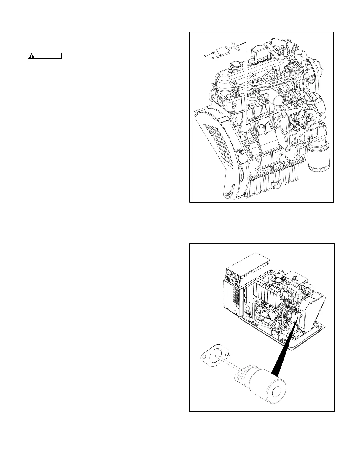
The genset controller modulates the pulse width of
the current it sends to governor actuator A12 (Fig-
ure 5-10 or 5-11), which positions the engine fuel
rack accordingly.
If troubleshooting indicates that the actuator might
be malfunctioning, disconnect its two leads and re-
move the actuator. Replace the actuator if the
plunger does not move smoothly when pushed in or
the internal spring does not return it smoothly. If the
plunger moves smoothly without binding, apply bat-
tery voltage (12 or 24 volts, depending on the gen-
set) and observe the plunger. Replace the actuator
if the plunger does not pull in all the way and stay in
while power is applied.
Reinstall the actuator with a new flange gasket.
Torque the two mounting screws to 7-9 lb-ft
(9.5-12.2 N-m).
GLOW PLUG RELAY (K3)
The glow plug relay is mounted on its wiring socket
inside the genset control box. Pull the relay out to
test it. Apply 12 VDC across terminals 85−86. Re-
place the relay if the contacts across terminals
30−87 (NO) do not open and close.
STARTER RELAY (K4)
The starter relay is mounted on its wiring socket in-
side the genset control box. Pull the relay out to test
it. Apply battery voltage across terminals 85−86.
Replace the relay if the contacts across terminals
30−87 (NO) do not open and close.
GROUND ISOLATION RELAY (K9)
See GROUND ISOLATION RELAY K9 (Page 6-6).
FIGURE 5-10. ACTUATOR A12—MDKBL, MDKBK,
MDKBM, MDKBN, MDKBT, MDKBU
FIGURE 5-11. ACTUATOR A12—MDKBP, MDKBR,
MDKBS
Redistribution or publication of this document,
by any means, is strictly prohibited.
 Loading...

