7-3
Exciter Stator
Winding Insulation Resistance: Disconnect gen-
set control connector P3. Connect pin P3-7 or P3-6
to the megger and conduct the test as instructed un-
der Winding Insulation Resistance Test Procedure.
Winding Resistance: Measure winding resistance
between pins P3-7 and P3-6. Replace the exciter
stator if the resistance is not as specified in
Table 7-1.
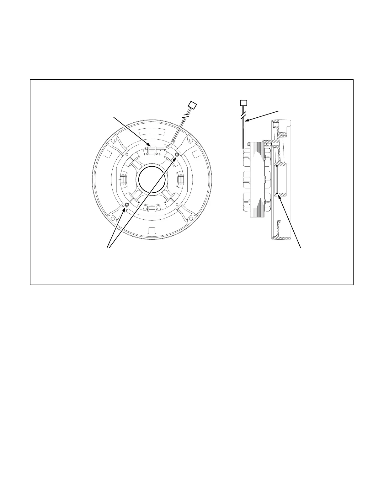
EXCITER STATOR LEADS
F1 (PIN P3-7) & F2 (PIN P3-7)
END BELL CASTING
ORIENT SO THAT FIELD COIL
WHERE LEADS ATTACHED IS UP
BEARING
BORE O-RING
STATOR MOUNTING SCREWS
8 LB-FT (11 N-M) TORQUE
FIGURE 7-2. EXCITER STATOR AND END BELL
Redistribution or publication of this document,
by any means, is strictly prohibited.
 Loading...

