The purpose of the engine governor is to maintain a
constant engine speed during changes in power
demands.
A
governor responds to changes in power
demands by varying the throttle position.
A
constant-
speed governor is standard on industrial engines.
GOVERNORS
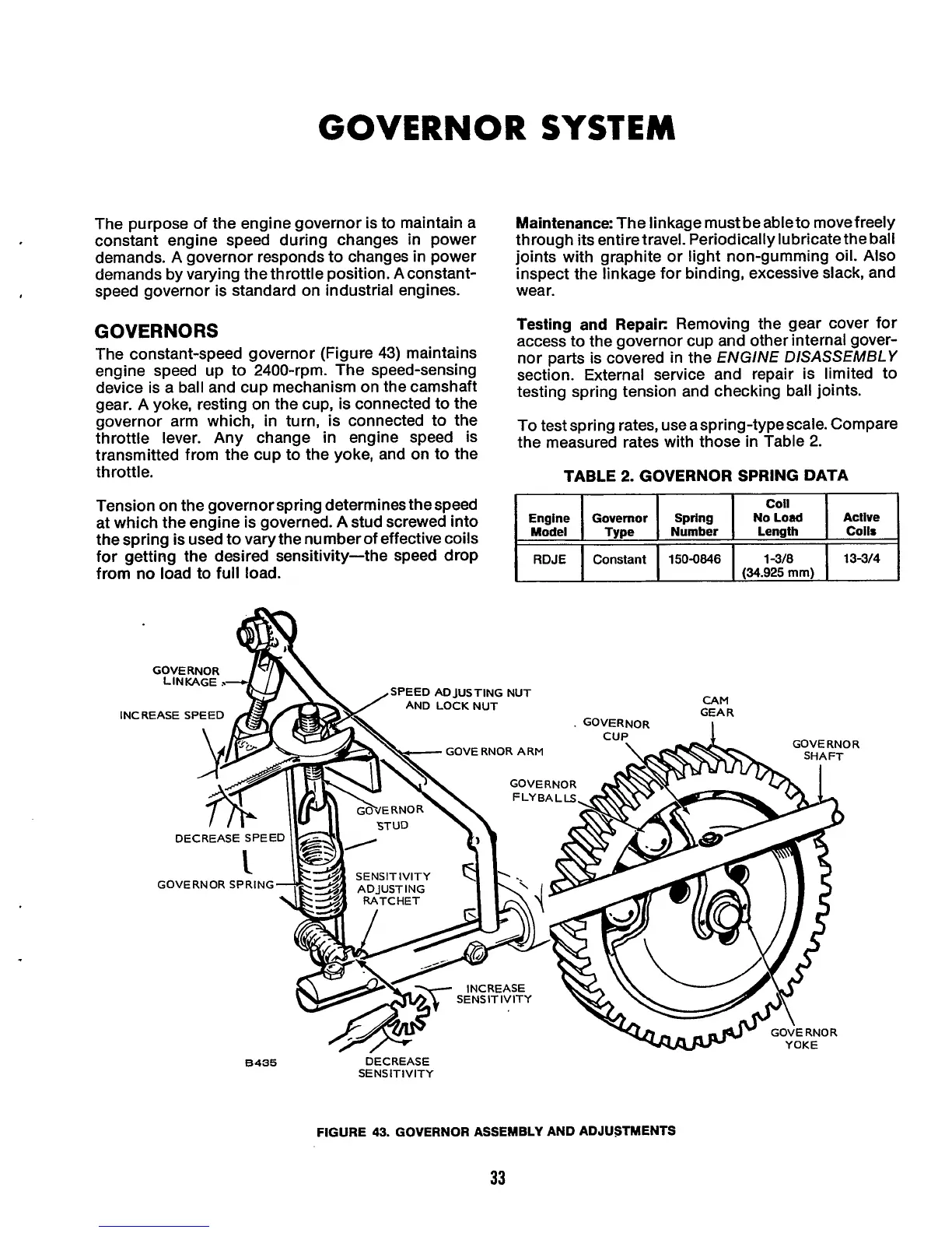
The constant-speed governor (Figure
43)
maintains
engine speed up to 2400-rpm. The speed-sensing
device is a ball and cup mechanism on the camshaft
gear.
A
yoke, resting on the cup, is connected to the
governor arm which, in turn, is connected to the
throttle lever. Any change in engine speed is
transmitted from the cup to the yoke, and on to the
throttle.
Maintenance:
The linkage must
be
ableto move freely
through its entiretravel. Periodically lubricate
the
ball
joints with graphite or light non-gumming
oil.
Also
inspect the linkage for binding, excessive slack, and
wear.
Testing and Repaie
Removing the gear cover for
access to the governor cup and other internal gover-
nor parts is covered in the
ENGINE DISASSEMBLY
section. External service and repair is limited to
testing spring tension and checking ball joints.
To
test spring rates, use aspring-type scale. Compare
the measured rates with those
in
Table 2.
TABLE 2. GOVERNOR SPRING DATA
Tension on the governor spring determines the speed
at which the engine is governed. A stud screwed into
the spring is used to vary the number of effective coils
for getting the desired sensitivity-the speed drop
from
no
load to full load.
Engine Governor Spring No
Load
Active
Constant
150-0846
1-3f8
13-m
1
;:
1
Type
1
Number
I
Length
I
Coils
I
(34.925
mm)
8435
DECREASE
SENSITIVITY
FIGURE
43.
GOVERNOR ASSEMBLY AND ADJUSTMENTS
33
 Loading...
