Do you have a question about the Onan RDJE and is the answer not in the manual?
Consult and comply with all local, state, and federal codes.
Provide fire extinguishers, ensure fasteners are secure, and use caution near moving parts.
Avoid loose clothing and keep hands away from moving parts like PTO shafts, flywheels, and belts.
Disconnect batteries before servicing; avoid smoking due to explosive hydrogen gas.
Do not smoke or use open flames near fuel; use steel piping for fuel lines.
Exhaust gases are toxic; ensure proper ventilation and leak-free systems.
Do not open radiator cap when coolant is hot; monitor coolant levels.
Keep the unit and surrounding area clean; remove oily rags to prevent fire hazards.
Height, width, length, weight, cylinders, displacement, bore, stroke, and power take-off dimensions.
Clearances and dimensions for camshaft journals, tappets, and end play.
Clearances and dimensions for connecting rod bores and bearings.
Bore diameter, taper, and out-of-round specifications for cylinders.
Dimensions and clearances for crankshaft main and connecting rod bearings.
Clearances for pistons in cylinders and ring groove widths.
Clearances for piston pins in pistons and connecting rods.
Specifications for starter rotation, pinion clearance, and armature end play.
Stem diameter, guide clearance, and valve face clearance for intake valves.
Stem diameter, guide clearance, and valve face clearance for exhaust valves.
Length, outside, and inside diameters for valve guides.
Bore diameter, depth, seat width, angle, and oversizes for valve seats.
Load specifications for valve springs in open and closed positions.
List of specialized tools available from Onan for service and repair.
Torque values for various engine assembly components.
Causes and remedies for starting system issues.
Causes and remedies for fuel system related problems.
Causes and remedies for oil pressure and consumption issues.
Causes and remedies for governor control problems.
Causes and remedies for cooling system malfunctions.
Causes and remedies for internal engine component issues.
Checks and preparations before initial and subsequent engine start-ups.
Guidelines for warming up the engine and applying load to prevent issues.
Procedure for operating the engine periodically to prevent hard starting.
Procedures for protecting the engine when out of service for more than 30 days.
Steps for preparing a stored unit for service and operation.
Methods for starting engines in cold temperatures and general starting steps.
Procedures for engines equipped with optional automatic start/stop controls.
Steps to properly shut down the engine.
Recommended sequence for running in a new or rebuilt engine.
Checks for alignment and requirements for proper engine ventilation.
Routine checks for batteries and keeping the engine free of dust and dirt.
Effect of altitude on engine power and considerations for operation.
Recommendations for oil viscosity and fuel in low temperatures.
Steps to protect the engine when it will be out of service for more than 30 days.
Steps to follow when preparing a stored unit for operation.
Instructions for installing a short oil drain extension for service convenience.
Steps for removing and installing the oil filter.
Description of the fuel filter system components including sediment bowl and filters.
Importance of minimum back pressure for engine efficiency and valve life.
Recommendations for installing exhaust pipes and mufflers.
Interpreting exhaust smoke color to diagnose engine conditions.
Methods to suppress or reduce exhaust noise.
Consequences of a poor or clogged exhaust system on engine performance.
Locate exhaust outlet away from air inlet to prevent recirculation.
Install a condensation trap at the point of rise if exhaust is pitched upward.
Information on carbon monoxide, its symptoms, and prevention.
Description of water flow through the radiator cooled system.
Details on the centrifugal water pump, its mounting, and drive.
Requirements for inlet and outlet openings for radiator cooled models.
Importance of anti-freeze, corrosion prevention, and pressure cap function.
Recommendations for cleaning and flushing the cooling system annually.
Procedure for draining the cooling system for service or storage.
Step-by-step guide for flushing the cooling system.
Procedure for removing air from the cooling system for proper operation.
Steps to test the thermostat for sticking or faulty operation.
Instructions for tightening connections and using sealants.
Guidelines for managing fuel quality, tank types, and storage.
Overview of the fuel system including sediment bowl, filters, and pump.
Requirements for installing fuel tanks and lines, including gravity feed avoidance.
Connecting fuel supply and return lines, using flexible lines, and ensuring no air leaks.
Description of the diaphragm pump operation and priming lever.
Checking fuel pump pressure and vacuum capacity.
Step-by-step instructions for removing and disassembling the fuel pump.
Information on common fuel pump failures and available repair kits.
Description of the hydraulically-operated, pintle-type injection nozzles.
How high-pressure fuel is injected into the combustion chamber.
Checking the spray pattern to diagnose misfiring cylinders.
Procedure for adjusting nozzle opening pressure using a testing fixture.
Steps for disassembling injection nozzles and handling components.
Using a nozzle tester for checking opening pressure, leakage, and spray pattern.
Detailed steps for cleaning injection nozzles using fuel and tools.
When cleaning fails, replace nozzle or take to authorized service station.
Instructions for thoroughly cleaning mounting recesses before installing nozzles.
How the fuel shutoff solenoid controls the injection pump operating lever.
Description of the 12-volt battery circuit for manifold heaters and glow plugs.
Information on the PSU injection pump used on Onan 2-cylinder diesels.
How the pump face gear and plunger are driven by the camshaft.
Internal view showing control unit, metering sleeve, delivery valve, and plunger.
How the metering sleeve is positioned by the governor control unit.
Procedure for removing the tappet from the pump body.
Importance of using correct shims for pump installation to ensure proper gear backlash.
Information on timing buttons and their role in pump timing.
Formula for determining the correct timing button thickness.
Explanation of timing button codes and their relation to dimensions.
Steps before installing the injection pump, including crankshaft positioning.
Aligning the PC mark on the flywheel with the timing pointer.
Instructions for mounting the pump using appropriate shims for backlash.
Steps for locking the drive gear and positioning the pump on the engine.
How the delivery valve maintains line pressure in injector lines.
Using fuel flow to determine and set the correct pump timing button.
Measuring port closing point relative to flywheel marks.
Calculating the required timing button thickness based on measurements.
Understanding timing marks on the flywheel for accurate timing.
Steps to bleed air from the fuel system after filter changes or air entry.
Description of the engine's pressure lubrication system.
Normal operating oil pressure requirements for the engine.
Location of the oil pump and how it is driven by the crankshaft.
Steps for removing the oil pump assembly.
Instructions for repairing or replacing the oil pump.
Location and function of the bypass valve in controlling oil pressure.
How to inspect the bypass valve for proper operation.
Procedure for flushing and cleaning oil lines and orifices.
Maintenance for oil lines, including flushing and cleaning.
Instructions for replacing the full-flow oil filter.
Description and maintenance of the crankcase breather system.
Installation of an oil drain extension for service convenience.
The function of the governor in maintaining constant engine speed.
How the governor senses speed and controls the throttle.
Periodic lubrication and inspection of governor linkage.
Methods for testing governor spring rates and ball joints.
How to adjust engine speed by changing governor spring tension.
How to adjust governor sensitivity to control speed droop.
Overview of the 12-volt starting motor, solenoid, and over-running clutch.
How the over-running clutch protects the starter from over-speed.
Troubleshooting poor cranking performance and testing the starter.
Checking battery charge condition using a hydrometer.
Procedure for testing starter stall torque using a spring scale.
Inspecting armature for mechanical defects, grounds, and shorted coils.
Checking field coils for grounding or open circuits.
Replacing starter bearings if excessive wear is present.
Checking brushes for wear and proper seating.
Cleaning the over-running clutch without using solvent.
Checking the movement and continuity of the shifting solenoid.
Steps for removing and disassembling the Prestolite starter motor.
Lubricating bronze bearings before assembling the starter.
Procedures for removing and installing the Mitsubishi starter.
Steps for disassembling the Mitsubishi starter motor.
Points where grease should be applied during starter assembly.
Adjusting pinion shaft end play using washers.
Installing the pinion gear and stop ring onto the pinion shaft.
Correct method for installing the lever assembly, spring, and packing.
Adjusting the pinion gap after starter assembly.
Steps for removing the voltage regulator and brush assembly.
Testing brush assembly continuity and shorts using an ohmmeter.
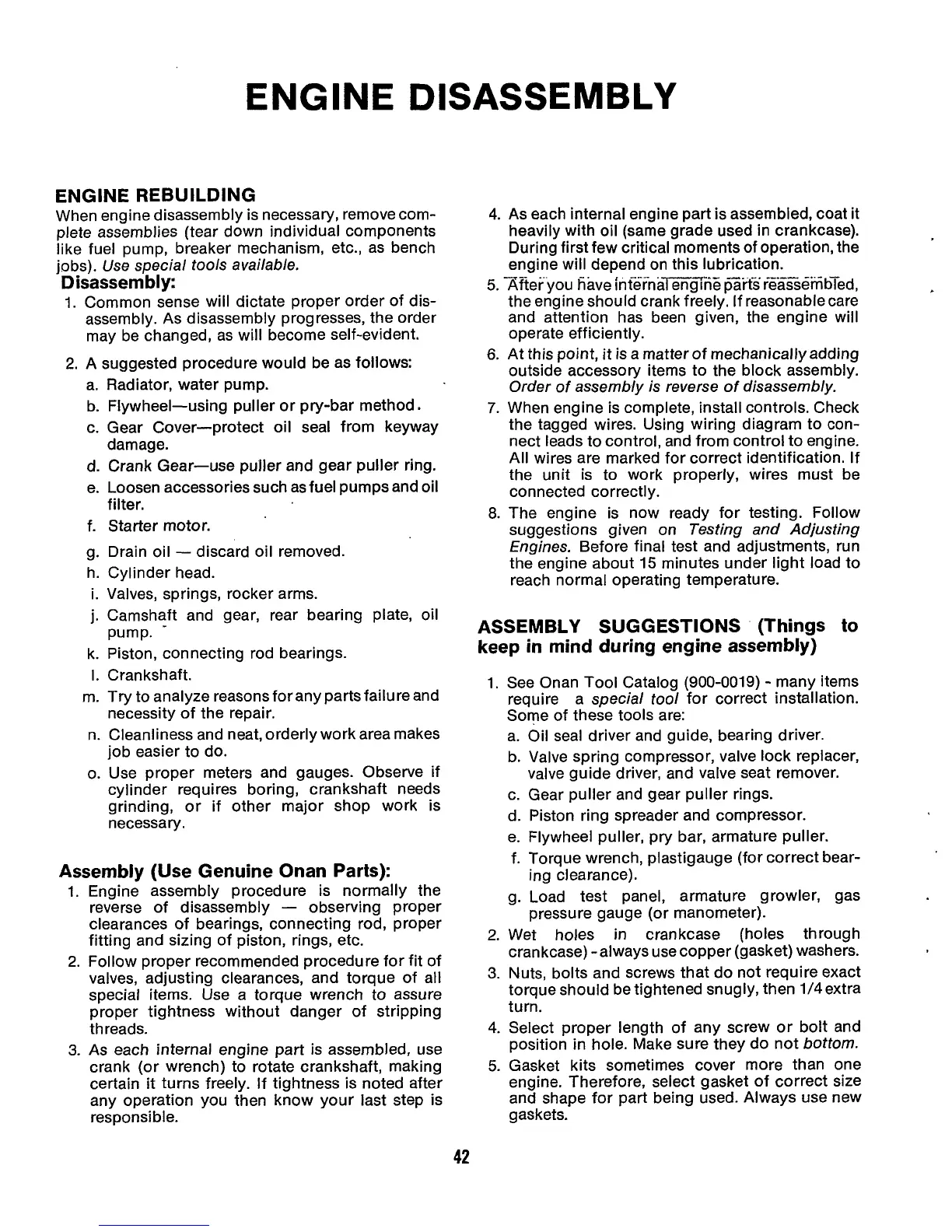
General approach to engine disassembly for rebuilding.
A suggested sequence for disassembling engine components.
Tips and considerations for engine assembly, including special tools.
General procedure for adjusting valve clearances.
Specific steps for adjusting valve clearance on RDJE engines.
Specific steps for adjusting valve clearance on RDJEA engines.
Checking and adjusting valve clearance using a feeler gauge.
Using a compression test to determine engine component condition.
Procedure for removing cylinder heads, rocker arms, and push rods.
Cleaning carbon deposits, checking valves, and refinishing valve seats.
Use of RTV sealant with cylinder head gaskets for water passages.
Instructions on where and how to apply RTV sealant to the gasket.
Steps for installing valve seals, valves, springs, and the cylinder head assembly.
Specific sequence and torque values for tightening cylinder head bolts.
General order for internal engine disassembly and reassembly.
Using a puller to remove the flywheel from the crankshaft.
Fitting replacement flywheels and determining TDC and port closing points.
Methods for removing and installing the flywheel ring gear.
Steps to remove the gear cover and governor components.
Procedure for removing the governor shaft and its bearings.
Instructions for replacing the gear cover oil seal.
Steps for assembling the gear cover, governor shaft, and checking dimensions.
Procedure for removing the governor cup from the camshaft.
Description of pistons, rings, and their installation.
Inspection of connecting rods and checking bushings for clearance.
Steps for removing piston assemblies from the cylinder.
Checking cylinder walls for scratches, pitting, and wear.
Cleaning and inspecting pistons for scoring or wear.
Checking piston pin fit in the piston at room temperature.
Inspecting rings for fit in piston grooves and seating on cylinder wall.
Checking connecting rod bearings for defects and wear.
Installing pistons, rings, connecting rods, and caps with proper torque.
Steps for removing rocker arms, push rods, and the camshaft assembly.
Dressing scored lobes or replacing worn or scored camshafts.
Pressing new camshaft bearings into place ensuring proper alignment.
Installing camshaft gear, governor components, and checking end play.
Steps for removing the crankshaft from the crankcase.
Cleaning crankshaft and checking journals for wear or damage.
Pressing main bearings into place and aligning oil holes.
Checking and adjusting crankshaft end play using shims.
Considerations when replacing the crankcase, including pump shims and retiming.
Procedures for running in an engine after new rings or pistons are installed.
Engines are adapted for various uses; controls are typically provided by the fabricator.
Periodically checking control system connections for tightness and cleanliness.

