EasyManua.ls Logo

Onkyo TX-DS595 Service Manual

Onkyo TX-DS595
71 pages
To Next Page IconTo Next Page
To Previous Page IconTo Previous Page
Page #13 background imageLoading...
Page #13 background image
1
2
3
4
5
6
7
8
16
15
14
13
12
11
10
9
MON
GND
IN5
GND
IN4
CTRE
IN3
CTLD
IN1
CTLA
VOUT1
VDD
IN2
CTLB
VOUT2
CTLC
LOGIC
6dB
LOGIC
6dB
#15
A
L
H
L
H
H
#11
B
L
L
H
H
H
#6
E
X
X
X
L
H
#1
MONITOROUT
IN1
IN2
IN3
IN4
IN5
#9
C
L
H
L
H
H
#8
D
L
L
H
H
H
#6
E
X
X
X
L
H
#14
VOUT1
IN2
IN3
IN4
IN5
#15
A
L
H
L
H
H
#11
B
L
L
H
H
H
#6
E
X
X
X
L
H
#14
VOUT2
IN1
IN2
IN3
IN4
IN5
X:Don'tcare
6.2dB
AMP.
CLAMP
2.0kohm
2.2kohm
75ohm
Driver
750ohm
Vout2
V
SAG2
SAGcorrection
6.2dB
AMP.
CLAMP
2.0kohm
2.2kohm
75ohm
Driver
750ohm
Vout2
V
SAG2
SAGcorrection
8
1
7
5
6
4
3
2
V+
GND
V
IN2
V
IN1
BU1923(RDS Decoder)
+
(4)
(3)
(5)
(6)
(12)
(11)
(16)
(1)
(2)
(10)
(9)
Measurement
circuit
Differential
decoder
Bi-phase
decoder
PLL
1187.5Hz
PLL
57kHz
RDS/ARI
Reference
clock
(13) (14)
(7)
(8)
Analog
Power supply
Digital
power supply
anti-aliasing
filter
8ch Switched
capacitor filter
Comparator
RCLK
QUAL
RDATA
T2T1
XO
X1
VSS2
VDD2
VSS1
VDD1
VREF
MUX
VSS3
CMP
BLOCK DIAGRAM
TX-DS595/696
BA7625(Video Select Switch)
NJM2296D(Dual Video 6dB Amplifier with 75ohm Driver))

Other manuals for Onkyo TX-DS595

Question and Answer IconNeed help?

Do you have a question about the Onkyo TX-DS595 and is the answer not in the manual?

Onkyo TX-DS595 Specifications

General IconGeneral
Channels5.1
Dolby ProcessingDolby Digital, Dolby Pro Logic
Component Video SwitchingNo
Remote ControlYes
Total Harmonic Distortion0.08%
Input Sensitivity200 mV
Signal to Noise Ratio100 dB
Output Level200 mV
Frequency Response10 Hz-100 kHz
Speaker Impedance6-16 ohms
Tuner TypeAM/FM
Preset Stations40
OutputsA/V output, audio output, subwoofer output
Output Impedance2.2 kOhms
Video Inputs3
Video Outputs1
Audio Inputs6
Audio Outputs2
Inputs1 phono
Weight21.6 lbs

Summary

Safety Warnings and Checks

Leakage Current and Resistance Measurements

Safety check for insulation before returning appliance to customer.

Service Procedures

Fuse Replacement Procedures

Instructions for replacing fuses, including part numbers and types.

Unit Initialization and Safety Checks

Procedures for resetting the unit and performing post-service safety checks.

IC Block Diagrams and Descriptions

Digital Interface ICs

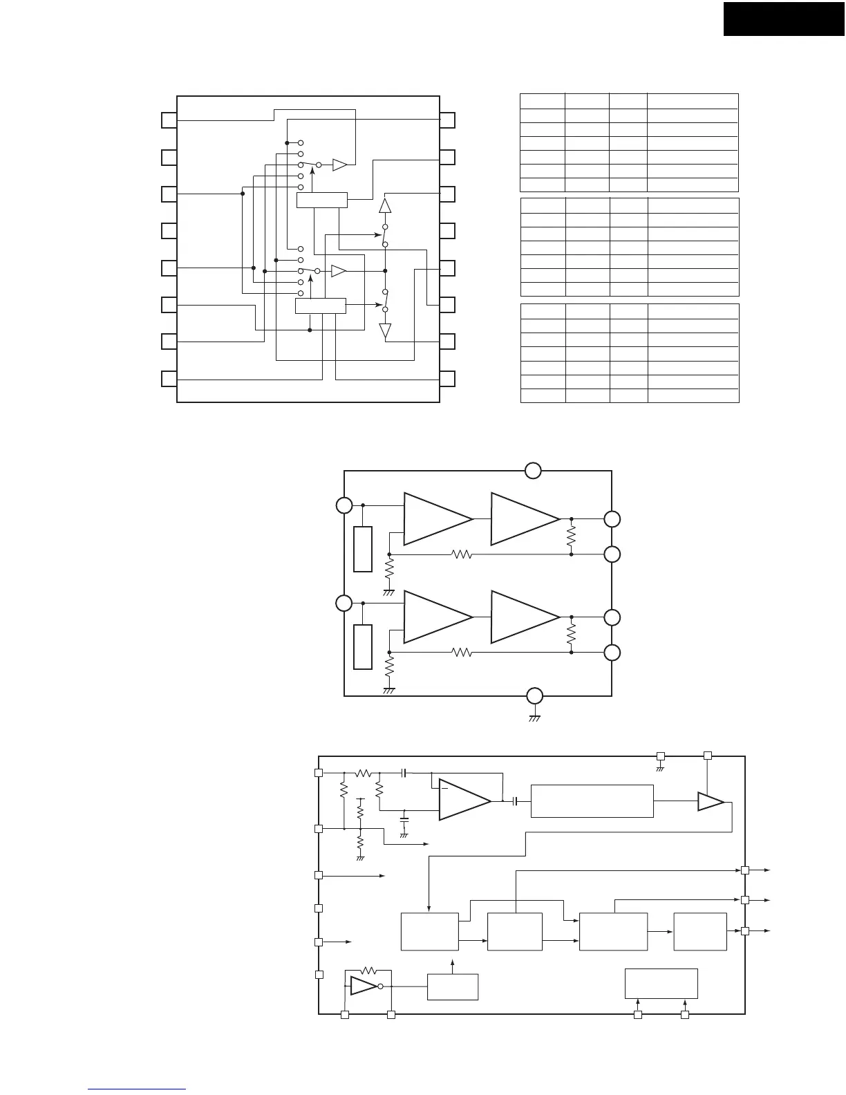
Block diagrams and pin descriptions for digital interface ICs.

CODEC and Video ICs

Diagrams for CODEC, video amplifiers, and RDS decoder ICs.

Analog Switch, Buffer, and Indicator ICs

Diagrams for analog switches, bus buffers, and TV indicators.

Volume Control IC Description

Block diagram and terminal description for the TC9482N volume control IC.

Microprocessor Terminal Descriptions

Main Microprocessor Pin Descriptions

Detailed pinout and function descriptions for the main microprocessor.

Sub Microprocessor Pin Descriptions

Detailed pinout and function descriptions for the sub microprocessor.

About Debug Mode

Debug Mode Entry and Investigation

How to enter debug mode and compare displays for troubleshooting.

Display Information Interpretation

Explains DIR ERROR, DIR STATUS, and analog/digital signal judgment displays.

DSP Signal Judgment and Decoding

Interpreting DSP input signal detection and decode status for troubleshooting.

Block Diagrams

Overall System Block Diagram

High-level diagram showing major functional blocks and signal flow.

Schematic Diagrams

Input Section Schematics

Detailed circuit diagrams for the input stages of the receiver.

Adjustments and Confirmation Procedures

Related product manuals