ABOUT DEBUG MODE
ch
f
t
DIRECT
DS
P
RDS
SLEEP
MEMORY
SPEAKERS
FM MUTE
PC
M DIGITAL
TUNED
FM STEREO
dB
STEREO
AB
MPEG
DTS
AUTO
STANDBY
1 2 3 4 5 6 7 8 9 1 2 3 4 5 6 7 8 9
1. How to enter the debug mode
Press and hold down the AUDIO SEL button, then press
the STANDBY/ON button to display "DEBUG MODE IN".
After 5 second the unit enters the DEBUG mode.
When there is the error that can judge by the microprocessor,
the error message is displayed for 3 seconds.
DSPREAD ERROR: Problem of interface between DSP and
microprocessor.
DSPLOCK ERROR: Problem of lock of DSP IC.
On all occasions the microprocessor resets DSP, and DSP is
restarted.
2. How to investigate the unit by the debug mode
Apply the signal that the trouble occurs, and compare with
the example of display or the normal unit. If there is
difference on the display, you are able to check the rejection
by the explanation below. If there is not difference, the input
signal comes to DSP IC and the format of signal is recognized.
Check the signal from the DSP output to the speaker output.
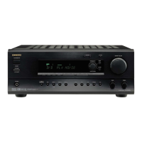
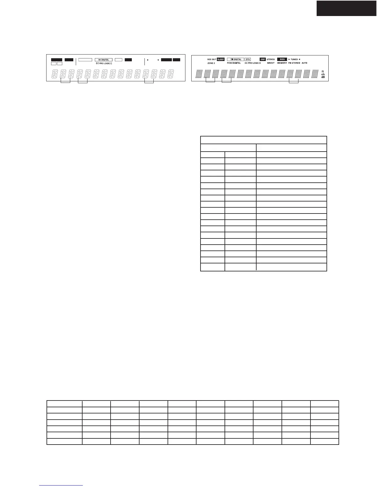
3. Explanation of Display
1. DIR ERROR: Check of digital signal of DIR IC (AK4112).
L:There is the digital signal. H:No digital signal.
When apply the digital signal, the display is "L".
Check the circuit from digital input to DIR IC and the
connection between ERF (#18) of DIR and microprocessor.
2. DIR STATUS 1: It displays the status of Addr03H that
AK4112 reads from the digital signal. It shows the sampling
frequency, and pre emphasis etc. When the display is difference
to the table below, check the signals of DSPCL and DSPDA to
confirm the communication between the microprocessor and
CDTO/SCDO(#28) of AK4112.
3. DIR STATUS 2: It displays the status of Addr0DH that
AK4112 reads from the digital signal. It shows the constants of
input signal (DD,DTS,MPEG etc.). When the display is difference
to the table below, check the signals of DSPCL and DSPDA to
confirm the communication between the microprocessor and
CDTO/SCDO(#28) of AK4112.
4. DIR analog/digital judgment
It displays the result of judgment about input signal by the
microprocessor. D:Digital A:Analog
5-7. Addr15 -17 :These displays show the port condition of the flash
memory control. "L" except Japanese model.
DOLBY DIGITAL
MPEG AAC *1
DTS DVD
PCM 48K
PCM 96K
ANALOG
DIR ERROR
L
L
L
L
L
L
DIR STATUS1
34 or B4
34 or B4
34 or B4
04
03 or 05
**
DIR STATUS2
01
07
0B
**
**
**
ANA/DIG
D
D
D
D
D
A
ADDR15
L
L
H
L
L
H
ADDR16
L
H
L
L
L
L
ADDR17
H
L
L
L
H
H
Judgment
01
07
0B
23
23
23
DECODE
1
1
1
1
1
1
8. Judgment of DSP input signal
It displays the result of detection about the input signal
by DSP IC. Refer to the table below.
When the display differs, check the DSP IC and
circumference of DSP IC.
00
01
02
03
04
05
06
07
08
09
0A
0B
0C
0D
00
01
02
03
04
05
06
07
08
09
0A
0B
0C
0D
20
21
22
23
Null
Dolby Digital
Reserved
Pause
MPEG1 L1
MPEG1 L23/MPEG2 w/e
MPEG2 w/e
MPEGAAC
MPEG2 L1
MPEG2 L2/3
Reserved
DTS1(512)
DTS2(1024)
DTS3(2048)
Silent
DTS LD
DTS CD
Linear PCM
Digital Signal Detection
DIR STTS2 DSP
9. DSP DECODE
When there is the input signal in DSP IC.
"1" : When decode the signal.
"0": When does not decode the signal.
"0":When there is not the input signal in DSP IC.
When the digital signal is applied in DSP IC,
the display is "0".
DSP IC does not operate.
Check the signals to the pins 22, 25, and 26 of
DSP IC.
Is there the signal to pin 20 of DIR IC?
*1: Japanese model only **:State of last input
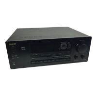
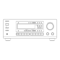
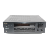
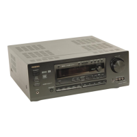
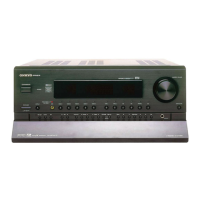
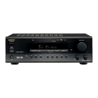
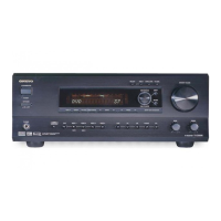
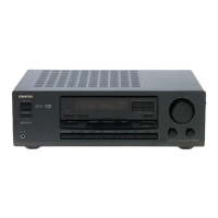
TX-DS595
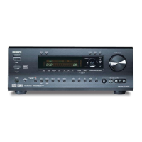
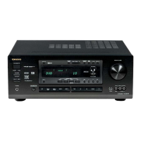
TX-DS696
TX-DS595/696
 Loading...