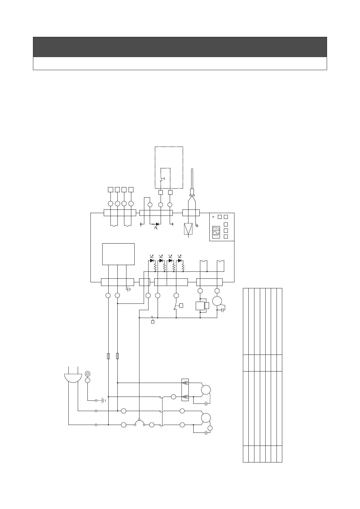
54
Wiring
■RKS400F-S
CN6
CN5
CN7
2
E
K4
K3
K2
K1
E04
E03
E02
E01
circuit
Control
CN4
CN2
CN1
CN3
4
5
1
1
1
3
5
7
2
1
1
3
1
3
1
7
9
3
5
MC1
C3
M3
SK
A2/b A1/a
TS
PRS
P
F2(1A)
F1(1A)
C1
C2
Red
M2M1
S
R
C
MP
MC1
N1
L1
R2
U2
V1
U1
2
1
3
4
5
S
N
L
ENL
AC100V 50/60Hz
16
14
15
15
14
13
12
11
10
10
11
12
13
θ
Controller
(Closed at alarm)
(Closed at operation)
Alarm signal
Operation signal
for remote control
Terminal block
Wiring by customer
sensor
Temperature
circuit
Temp.detect
Yellow
Blue
2
3
1
6
4
5
3
1
2
MC1
MP
Operation condenser
C1〜3
short-circuited 10mA to 17mA
○represents wire number.
* □represents terminal block number.
DC5V 10mA
・Voltage when circuit is open DC11V to DC18V
・Input resistance 1kΩ
・Current when circuit is
・Maximum length of wire 20m within.
(Alternate)
・Input of non-voltage contact
2.Input of remote control
・Relay output a contact
(reference value)
・Minimum use current
3A(Resistance load)
・AC250V/DC30V
1.Output of alarm signal
Motor(Circulation pump)
Motor protector
Fuse
F1,2
Electromagnetic contactor for M1
Motor(Fan)
Motor(Compressor)M1
M2
M3
Symbol Name of parts
Temperature switch
SK
TS
Relay
K1〜5
ConnectorCN1〜7
High-pressure switch
Spark killer
PRS
Symbol Name of parts
 Loading...