Page 18
900-0093-01-00 Rev C
©2020 OutBack Power. All Rights Reserved.
Common Problems
Symptom Possible Cause Possible Remedy
Current readings are inaccurate or
reversed.
Shunt(s) miswired. Confi rm correct wiring on all shunts.
See page 5.
Current reading is zero with current
confi rmed present.
Shunt not enabled. Enable all shunts that are in use.
See page 7.
Current or SOC readings are
inaccurate.
Unused shunt is still enabled and is picking
up electrical noise.
Disable any shunts not in use.
See page 7.
SOC readings are inaccurate. SOC setting was not set to match
battery capacity
.
Unit was not configured and was left
at factory defaults; the factory default
settings may not be accurate for a
given system.
System has not been through a
complete charge cycle recently.
Multiple partial charge cycles can
introduce errors.
Battery charger settings are not
accurate for the system.
Along
with potentially undercharging the
batteries, this can cause the MATE3s
Charge Termination Control to stop
charging at the wrong time.
Charge Factor is set inappropriately
for the batteries.
FN-DC may require calibration.
Ensure the SOC setting matches the
rated capacity of the battery bank.
See page 7.
Follow all programming instructions.
See page 6.
Ensure the SOC setting matches the
rated capacity of the battery bank.
Ensure the full-charge settings
in Battery Setup match both the
charger settings and the battery
manufacturer's requirements.
See page 7.
Complete one or more full charge cycles,
then begin discharging the batteries to
force a reset.
Check all settings and follow all
programming instructions. Set the
charging source according to the
battery manufacturer’s requirements.
Set
Charge Factor according to the
battery manufacturer’s requirements.
See page 7.
See FN-DC Field Calibration.
Aඝච relay is not operating according to the
previous settings.
A reset to factory defaults may have reset
the relay settings to a 12-volt system.
Set
FLEXnet Relay Set Points to the voltage
and other settings appropriate to the system.
See pages 12 and 13.
Battery voltage reading is not accurate. FN-DC may require calibration. See FN-DC Field Calibration.
Troubleshooting
Page 3
Installation
Installing the FLEXnet DC
The FLEXnet DC mounts in a ¾" DC circuit breaker slot installed inside an OutBack Power load center.
To mount the FLEXnet DC inside an OutBack Power enclosure:
1. Put the system into bypass mode.
2. Shut off all AC input to inverters.
3. Shut off all PV and DC breakers.
4. Disconnect the battery cables at the battery.
5. Remove the breaker bracket from its enclosure by removing the four corner screws.
6. Remove one of the DC breaker knockouts.
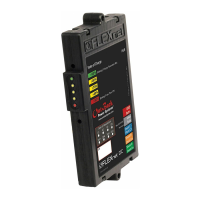
7. Insert the FN-DC unit into the rear of the breaker bracket so that the indicator lights fi t in the breaker opening.
8. Mount the FN-DC securely using the two #6-32 screws provided.
Remove breaker knockout and install FN-DC
using 2 #6-32 × ⅜" pan-head machine screws
provided (torque to 5 to 8 inch-pounds).
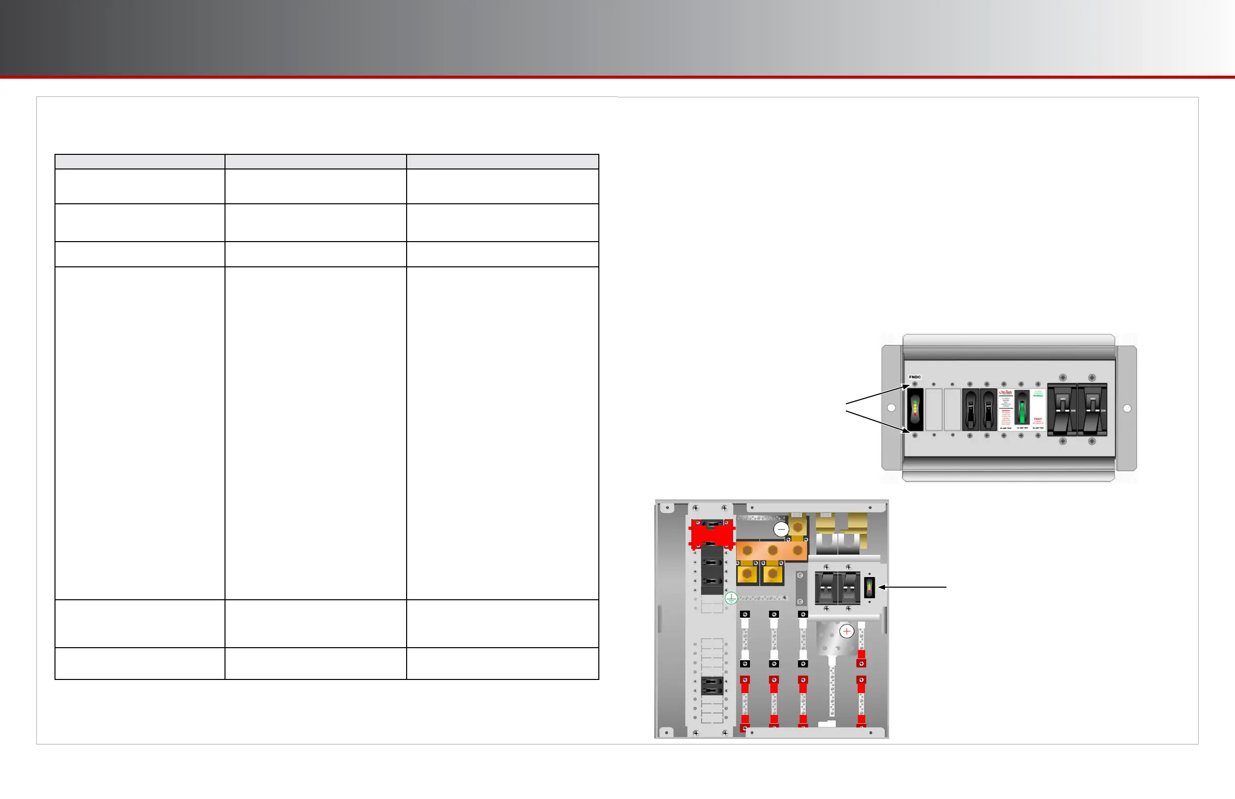
The FN-DC mounting location will vary depending on
the system. Here, for example, in the GSLC, the
FN-DC is mounted adjacent to the main DC breakers
for the battery bank.
 Loading...