Page 12
900-0093-01-00 Rev C
©2020 OutBack Power. All Rights Reserved.
Programming the Auxiliary Relay
The FLEXnet DC provides an auxiliary (Aඝච) relay to activate a DC accessory like a ventilation fan or light.
The Aඝච relay is a "dry contact" that does not supply power. The contacts are rated at 5 amps @ 30 Vdc.
The relay requires appropriate sized wiring and overcurrent protection. Note that damage due to unprotected
relay devices is not covered by the warranty.
Confi guring and monitoring is done with the MATE3s system display (or OPTICS RE). See page 6 of this
document for specifi c steps to access the relay settings in the MATE3s.
FLEXnet Relay Mode
This menu allows the user to turn the Aඝච relay on or off ,
either manually or using automatic criteria.
○ Status — The Relay output status is controlled by the
<Off>,<Auto>, and <On> soft keys.
● <Off> deactivates the relay and prevents any of the FLEXnet Relay Set Points options from working.
Note that even if the relay output is set to <Off>, it may still be activated by an external option
such as AGS.
● <On> activates the relay immediately. Its contacts will remain continuously closed until <Off> is selected.
● <Auto> activates the relay based on user-selected battery voltage, percentage of SOC, delay times, and
invert logic settings. In the FLEXnet Relay Set Points menu, six user adjustable set points govern the
control logic of Auto mode:
◘ Voltage: High — 0 to 99.9 Vdc
◘ (Voltage) Low — 0 to 99.9 Vdc
◘ SOC: High — 0 to 100%
◘ (SOC) Low — 0 to 100%
◘ Delay: High — 0 to 240 minutes
◘ (Delay) Low — 0 to 240 minutes
○ Invert Logic — N (no) or Y (yes).
This switches the relay‘s function from N.O. (a normally open state) to N.C. (a normally closed state). Since
the default condition is N.O., the N selection means it remains in this state. Selecting Y inverts the logic to
N.C. The relay will close with an audible click when this occurs.
Operation
NOTES
If the Voltage set points are not met, then the SOC set points are evaluated.
If SOC set points are not met, then no action is taken.
If either Voltage or SOC set points are met, then the Delay timer runs.
When the set points have been satisfied for a Delay time (either Delay: High for the Voltage: High
or SOC: High set points), or (Delay) Low for the Low set points) the relay is energized.
To defeat the Voltage set points and skip directly to using SOC, change Voltage: High to a very high
setting (higher than the operating range of the battery). Change Low to a similarly low setting.
Page 9
Operation
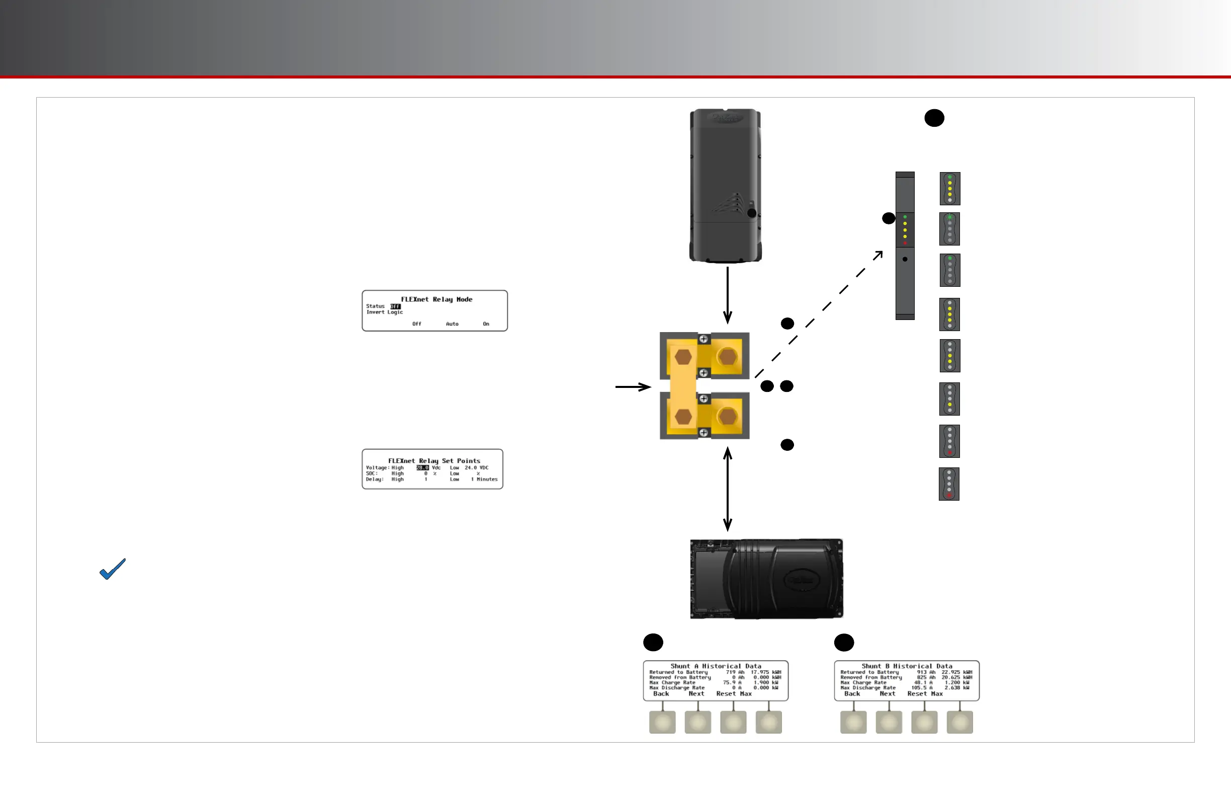
Shunt A Historical Data
FN-DC LED Indicators
The FN-DC indicates the battery bank’s SOC with a set
of 5 LED indicators. These are displayed in the breaker
panel opening where the unit is installed. See page 3.
All yellow and green LED indicators lit:
90-100% SOC
Green LED indicator blinking:
charge parameters met
Green LED indicator solid:
SOC above 90%
All yellow LED indicators lit:
80-89% SOC
Two yellow LED indicators lit:
70-79% SOC
One yellow LED indicator lit:
60-69% SOC
Red LED indicator solid:
50-59% SOC
Red LED indicator blinking:
Less than 50% SOC
B
B
J
K
J
K
D I
Shunt B Historical Data
Current from
charge controller
Current into
and out of
inverter
Shunt A
Shunt B
Charge
Controller
Inverter
Communications
to FN-DC
,
 Loading...