Page 16
900-0093-01-00 Rev C
©2020 OutBack Power. All Rights Reserved.
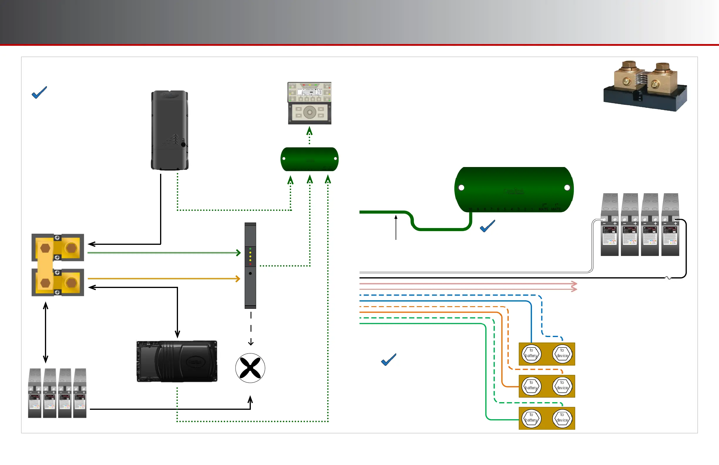
Example Use Cases
One Inverter, One Charge Controller
Current into
and out of
batteries
Current from
charge controller
Current into
and out of
inverter
Shunt A
Shunt B
FLEXmax
Charge
Controller
Inverter
Vent Fan
Power supply to Aඝච load
Aඝච signal
to fan
FN-DC
communications
to HUB
FLEXmax
communications
to HUB
Inverter
communications
to HUB
HUB
communications to
MATE3s
Shunt B measurement to FN-DC
Shunt A measurement to FN-DC
NOTE:
Other confi gurations or systems are
possible from what is depicted here.
Other shunt designations are also
possible, as any device may be placed
on any shunt. The layouts shown on
these pages may be diff erent than
factory-built systems.
Battery Bank
Page 5
CAT5 Cable
Installation
Shunt Operation
The FN-DC uses shunts to measure electrical current. A shunt works by
creating a low-resistance path for current between two points, resulting in
a small voltage drop that can be measured and converted to amperes of
current. The FN-DC can connect to as many as three shunts in order to
monitor current between the battery bank and devices like an inverter or
a charge controller. A typical setup uses one shunt to measure current between the battery bank and an
inverter; a second shunt to measure current fed into the battery bank from a solar array charge controller; and
a third shunt to measure a second charge controller. By tracking the current fl owing into and out of a
battery bank, as well as voltage, the FN-DC can monitor the battery bank’s state of charge (SOC) more
accurately than by simply tracking voltage. See page 14 for a more detailed discussion of SOC.
NOTES
The FLEXnet DC shunts must
be connected to the negative
(low) side of whatever device
they monitor to avoid damaging
the FN-DC.
Shunts must have a 1:10,000
ratio with a maximum current
1000 amps.
Relay wires connect to external
accessory. See page 12 for details.
Shunt C
Shunt B
Shunt A
NOTE
This diagram does not show the MATE3s
system display, which connects to the
HUB product and provides access to FN-DC
data and settings.
Hub
HUB
Communications
Manager
Battery Bank
 Loading...