Page 4
900-0093-01-00 Rev C
©2020 OutBack Power. All Rights Reserved.
Wiring
Block
Wiring Connections
Color-coded twisted pair #18 AWG connects the wiring block and
shunt(s) or battery. The wiring must be installed with the proper polarity
to avoid corrupting the data.
○ The wires connected to the wiring block should match the color-coded
label where the wiring block inserts into the FLEXnet DC.
○ The wiring block can accommodate wire sizes from #12 AWG to #26 AWG
(2.5 mm² to 0.20 mm²). Remove ¼" (6 mm) of insulation.
To connect the FN-DC:
1. Connect the white wire from the Bඉග– terminal in the
wiring block to the battery negative terminal; connect
the black wire from the Bඉග+ terminal in the wiring
block to the battery positive terminal.
NOTES:
Although the image shows the Bඉග– and Bඉග + terminals wired
directly to the battery bank, it is common to wire them to the
positive and negative bus connections in the load center. The
battery readings, however, will be most accurate when wired
directly to the batteries. It is prudent, though not required, to
install a fuse on the positive wire (see CAUTION).
2. Optional: connect relay wires from the Rඍඔඉඡ
terminals in the wiring block to a fan or other
powered accessory that can be triggered using dry
contacts (5 A @ 30 Vdc max.). See page 12.
3. Connect the blue / white wire from the wiring block
C Dඍඞඑඋඍ Sඑඌඍ terminal to the terminal of Shunt C
that connects to the device being monitored. Connect
the solid blue wire from the C Bඉග (–) Sඑඌඍ terminal to
the terminal of Shunt C that connects to the battery.
4. Connect the orange / white wire from the wiring block
B Dඍඞඑඋඍ Sඑඌඍ terminal to the terminal of Shunt B
that connects to the device. Connect the solid orange
wire from the B Bඉග (–) Sඑඌඍ terminal to the terminal
of Shunt B that connects to the battery.
5. Connect the green / white wire from the wiring block
A Dඍඞඑඋඍ Sඑඌඍ terminal to the terminal of Shunt A that
connects to the device. Connect the solid green wire
from the A Bඉග (–) Sඑඌඍ terminal to the terminal of
Shunt A that connects to the battery.
6. Tighten all wiring block terminal screws to a torque
value of 4 to 5 in-lb.
7. Connect the CAT5 cable from the FN-DC port labeled
Hඝඊ to the OutBack Communications Manager.
Installation
1
2
3
4
5
6
IMPORTANT:
Do not run these wires alongside
the battery cables. This can
induce voltage into the wires and
corrupt the data.
CAUTION:
Equipment Damage
Do not reverse the white and black
wires (see step 1). This will damage
both the FN-DC and the HUB
Communications Manager. Installing
a fuse on the positive wire (5 A
maximum, 100 Vdc minimum) may
help protect the devices.
Page 17
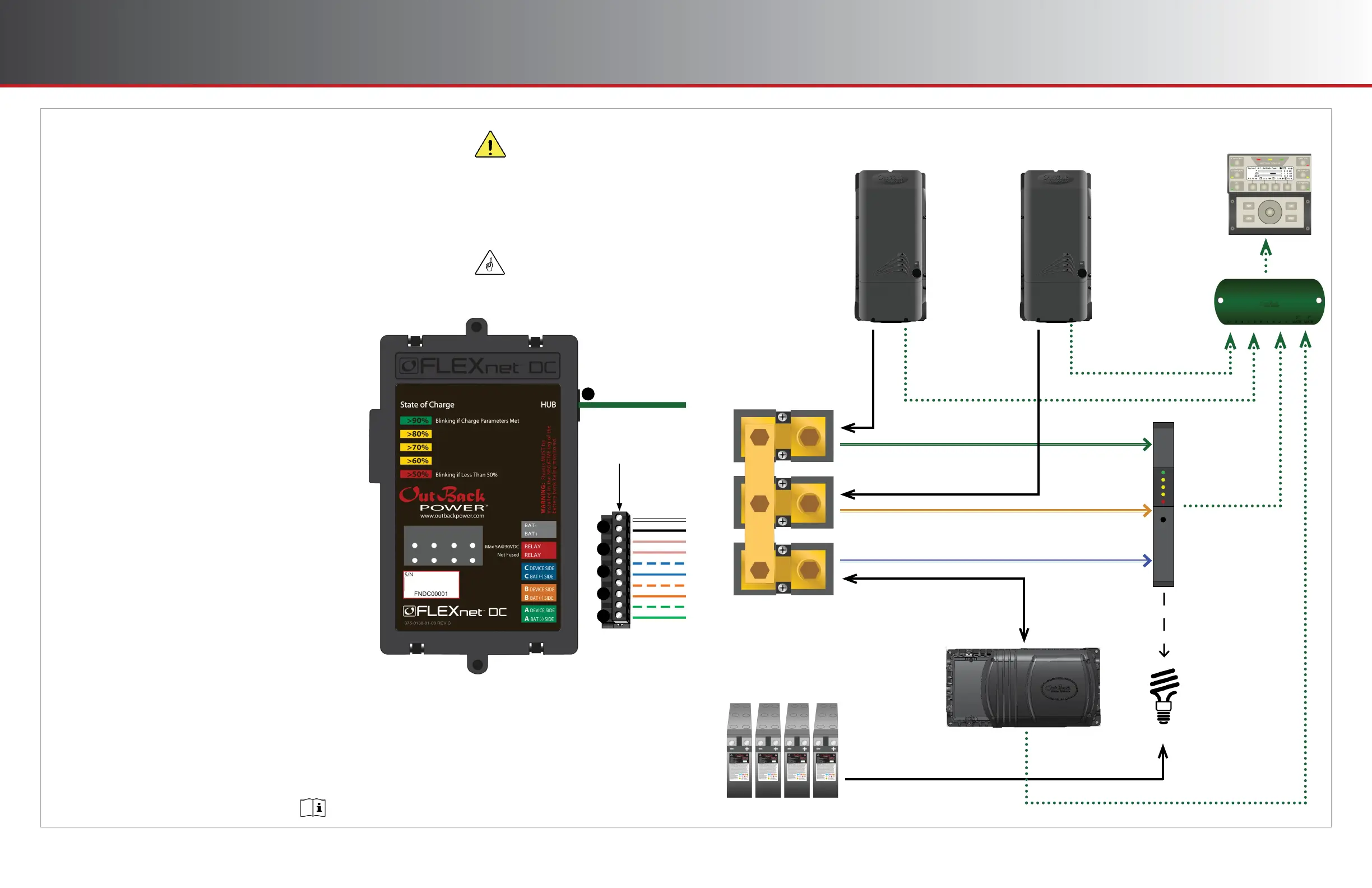
Example Use Cases
One Inverter, Two Charge Controllers
Current into
and out of
batteries
Current from
charge controller
Current into
and out of
inverter
Shunt A
Shunt B
FLEXmax
Charge
Controller
#1
Inverter
Shunt A measurement to FN-DC
Warning Light
Power supply to Aඝච load
Aඝච signal
to low-battery
warning
FN-DC
Communications
to HUB
FLEXmax #1
communications
to HUB
Inverter
Communications
to HUB
HUB
Communications
to MATE3s
Shunt C measurement to FN-DC
Shunt C
FLEXmax
Charge
Controller
#2
FLEXmax #2
communications
to HUB
Shunt B measurement to FN-DC
Use Port 2 or higher, depending on the requirements
of the configuration and the HUB literature.
 Loading...