21 WIRING MISTAKE PREVENTION
Improved quality of installation work through adoption of an “Connection error prevention” circuit which prevents wiring
mistakes
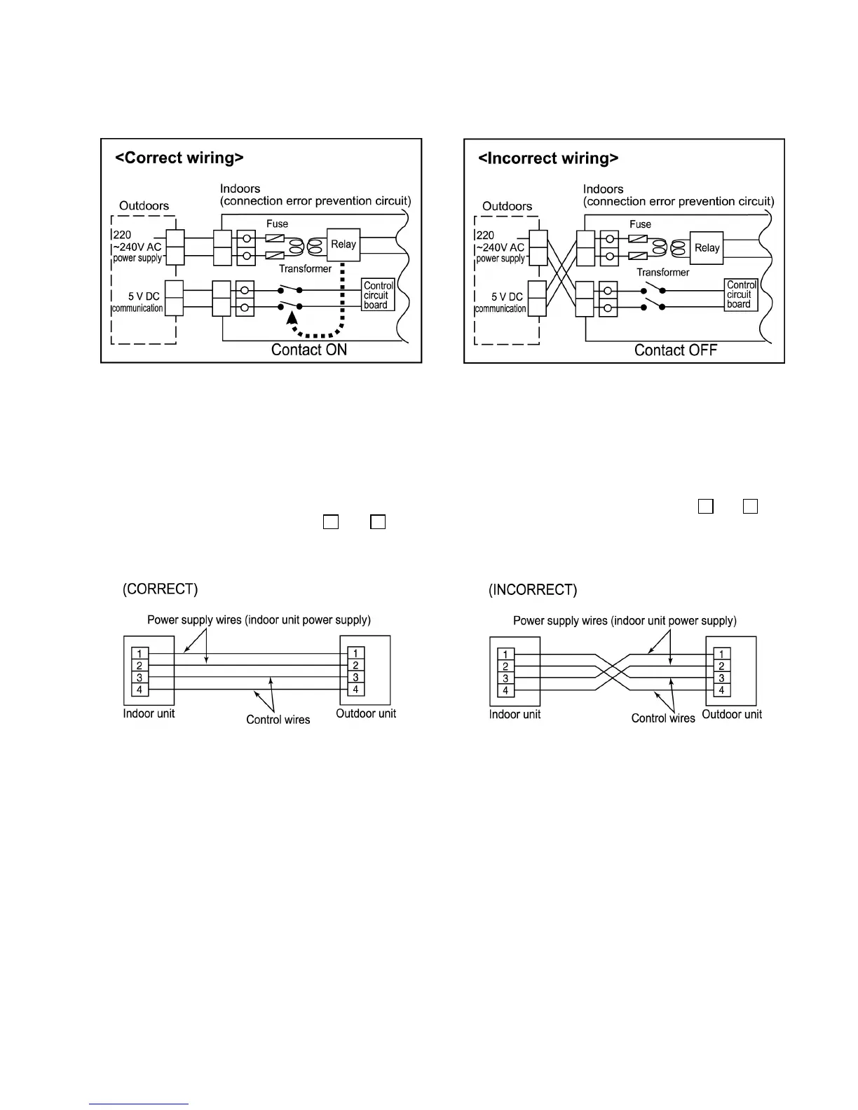
Connection errors with the control wires and the power supply wires will not only contribute to burning-out of the control circuit
board, but can also cause large-scale working losses and affect reliability. If a circuit board with a “Connection error prevention”
circuit is used, the relay will not operate if the wires have been connected incorrectly, so that current will not flow to the control
circuit board. This is designed principally to conpensate human error during installation.
Prevention of connection errors
These units are equipped with connection error prevention circuits. If the units do not operate, it is possible that the connection error
prevention circuits have been operated. In such cases, check that the power supply wires (connected to terminals 1
and 2 and
the control wires (connected to terminals 3
and 4 ) are connected correctly. If they are connected incorrectly, connect them
correctly. Normal operation should then commence.
•
• •
• Do not short the remote control wires to each other. (The protection circuit will be activated and the units will not operate.) Once
the cause of the short is eliminated, normal operation will then be possible.
NOTE:
•
• •
• Wait one minute after turning on the indoor unit power supply before operating the remote control.
•
• •
• If nothing at all appears in the remote control LCD, check the power supply for the indoor unit.
Refer to “TROUBLESHOOTING” chapter.
NOTE:
Do not allow any of the following connection, as such connection may damage the printed circuit board.
•
• •
• Do not connect anything except a relay to the timer input or fan speed output (connector CNT1 on printed circuit board).
•
• •
• Do not connect U-NET transmission wires to terminals 3 and 4 of the indoor and outdoor units. (*1)
•
• •
• Do not connect U-NET transmission wires to terminals A and B of the remote control.
(1*) U-NET transmission wires are the communication wires used for the central control.
47
 Loading...