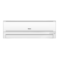
Fig. 4
− To remove the electronic controller.
− Release CN-FM connectors. (Fig. 4)
− Release CN-Sonic connector. (Fig. 4)
− Release CN-FB connector. (Fig. 4)
− Release CN-ION connector. (Fig. 4)
− Release CN-TH connector. (Fig. 4)
− Release CN-STM connector. (Fig. 4)
− Release CN-REC/DISP connector. (Fig. 4)
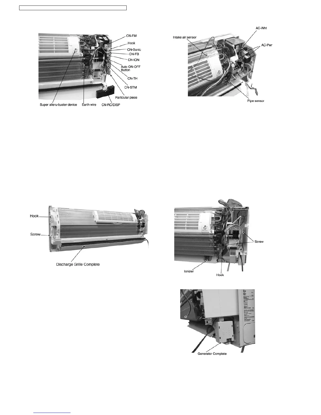
• Remove Control Board Cover
Fig. 6
− Remove the screw on the left of the unit. (Fig. 6)
− Pull the hook to the left and lift up the evaporator.
(Fig. 6)
− Pull down the Discharge Grille Complete. (Fig. 6)
Fig. 5
− Press the hook to the right then take out the PCB. (Fig.
5)
− Release Ry-Pwr connector (black and brown) and Ac-
Wht connector from the PCB. (Fig. 5)
Fig. 7
Fig. 8
− Remove indoor pipe sensor and air intake sensor from
the evaporator. (Fig. 7)
− Remove the earth wire from the evaporator. (Fig. 7)
12.3. Indoor Fan Motor And Cross Flow Fan Removal Procedures
64
CS-A7DKD CU-A7DKD / CS-A9DKD CU-A9DKD / CS-A12DKD CU-A12DKD /
 Loading...