33
8.4. Lens Disassembly Procedure
Precaution:
1. Do not remove the CCD unit when disassembling or re-
assembling the lens in order to maintain it clean.
The screw fitting the CCD unit to the master flange unit is
fixed by the screw locking glue with the adjustment of the
installation angle of the CCD unit against the lens (optical
tilt adjustment) finished.
When remove it, refer to item "8.6.".
2. Keep dust or dirt away from the lens.
To remove dirt or dust from the lens, blow with dry air.
3. Do not touch the lens surface.
4. Use lens cleaning KIT (VFK1900BK).
5. Apply grease (RFKZ0472) as shown on "THE APPLICA-
TION OF GREASE METHOD" in the figure.
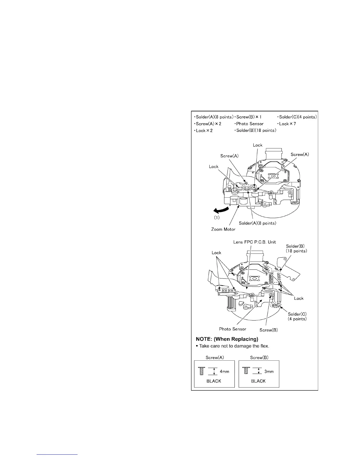
8.4.1. Removal of the Zoom Motor and
Lens FPC P.C.B. Unit
1. Remove the 8 solders (A).
2. Unscrew the 2 screws (A).
3. Remove the 2 locks.
4. Remove the zoom motor to the direction of arrow (1).
5. Unscrew the 1 screw (B).
6. Remove the photo sensor.
7. Remove the 18 solders (B).
8. Remove the 4 solders (C).
9. Remove the 7 locks.
10. Remove the lens FPC P.C.B. unit.
 Loading...