6
D1VW_EE 5715-690 UK.indd 11.07.22
Directional Control Valve
Series D1VW Explosion Proof
Operating Instructions
Parker Hannin Corporation
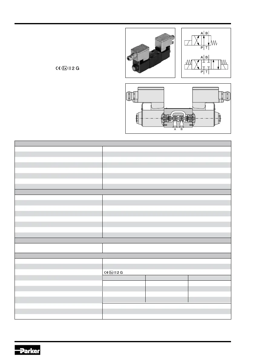
1. Introduction
The D1VW with explosion proof solenoids is ba-
sed on the standard D1VW series. The specic
solenoid design allows the usage in hazardous
environments.
The explosion proof class is
Ex e mb IIC T4 Gb
for use in zone 1 and 2 (according to ATEX).
Additionally the solenoids are IECEx compliant.
All explosion proof solenoids are DC design. The
valves for AC operate with integrated rectier.
Technical data
General
Design Directional spool valve
Actuation Solenoid
Size DIN NG06 / CETOP 03 / NFPA D03
Mounting interface DIN 24340 A6 / ISO 4401 / CETOP RP 121-H / NFPA D03
Mounting position unrestricted, preferably horizontal
Ambient temperature [°C] -20...+60
MTTF
D
[years] 150
Weight [kg] 1.8 (1 solenoid), 2.7 (2 solenoids)
Hydraulic
Max. operating pressure [bar] P, A B: 350; T: 210
Fluid Hydraulic oil according to DIN 51524
Fluid temperature [°C] -20 ... +60
Viscosity permitted [cSt] / [mm²/s] 2.8...400
Viscosity recommended [cSt] / [mm²/s] 30...80
Filtration ISO 4406 (1999); 18/16/13
Flow max. [l/min] 60 (see shift limits)
Leakage at 50 bar [ml/min] Up to 10 per ow path, depending on spool
Static / Dynamic
Step response at 95 % [ms] Energized: 32 (DC), 40 (AC)
De-energized: 40 (DC), 75 (AC)
Electrical characteristics
Duty ratio 100 % ED; CAUTION: coil temperature up to 135 °C possible
Max. switching frequency [1/h] 15000 (DC), 7200 (AC)
Protection class
, Ex e mb IIC T4 Gb, IP66 (plugged and mounted correctly)
Code
J N P
24 V = 230/50 Hz 110/50 Hz
±10 ±10 ±10
1.0 0.12 0.25
24 24 24
Supply voltage / ripple [V]
Tolerance supply voltage [%]
Current consumption [A]
Power consumption [W]
Solenoid connection
Box with M20x1.5 entry for cable glands. Solenoid identication as per ISO 9461.
Wiring min. [mm²] 3 x 1.5 recommended
Wiring length max. [m] 50 recommended
With electrical connections the protective conductor (PE W) must be connected according to the relevant regulations.
 Loading...