D1VW_EE 5715-690 UK.indd 11.07.22
Directional Control Valve
Series D1VW Explosion Proof
Operating Instructions
9
Parker Hannin Corporation
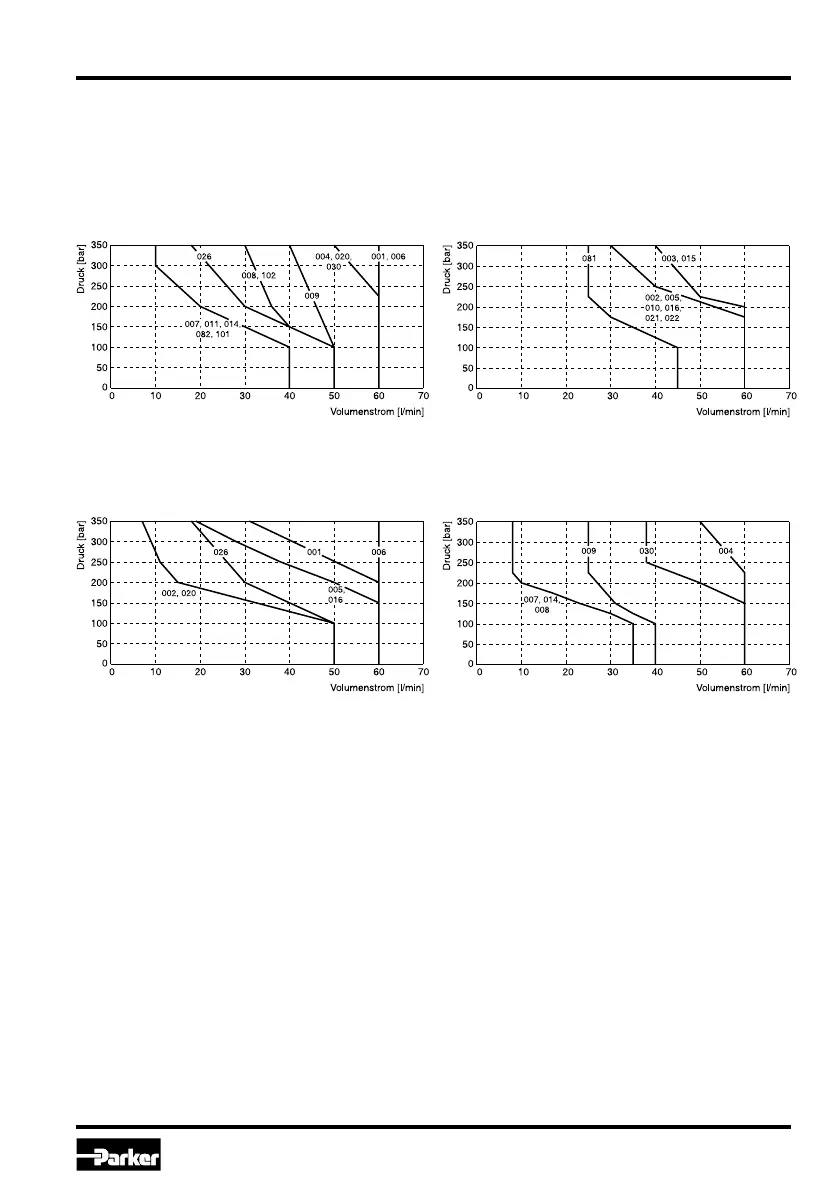
Shift limits
The diagram below species the shift limits for valves with AC and DC solenoids. The specications
apply to a viscosity of 40 mm²/s and balanced ow conditions. The shift limits can be considerably
lower at unbalanced ow conditions. To avoid ow rates beyond the shift limits, a plug-in orice can
be inserted in the P-port.
Shift limit diagram with DC solenoid
Shift limit diagram with AC solenoid
Measured with HLP46 at 50 °C, 90 % U
nom
and warm solenoids
Measured with HLP46 at 50 °C, 95 % U
nom
and warm solenoids
 Loading...