I
\ i i
ERON[
ID
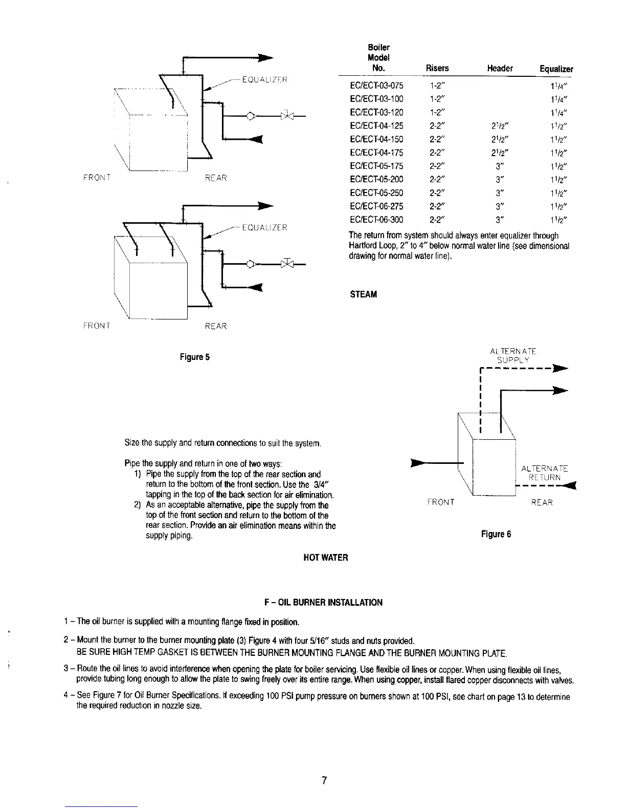
_ EQUALIZER
X
REAR
FRONT REAR
Boiler
Model
No, Risers Header Equalizer
EC/ECT-03-075 1-2" 11/4"
EC/ECT-03-1O0 1-2" 1V4"
EC/ECT-03-120 1-2" 1V4"
EC/ECT-04-125 2-2" 21/2', 11/2"
EC/ECT-04-150 2-2" 21/2", 11/2"
EC/ECT-04-175 2-2" 21/2" 11/2"
EC/ECT-05-175 2-2" 3" 11/2"
EC/ECT-05-200 2-2" 3" 11/2"
EC/ECT-05-250 2-2" 3" 11/2"
EC/ECT-06-275 2-2" 3" 1112"
EC/ECT-06-300 2-2" 3" 11/2"
Thereturnfrom systemshouldalwaysenterequalizerthrough
HartfordLoop,2" to4" belownormalwaterline (see dimensional
drawingfor normalwaterline).
STEAM
Figure5
Size thesupplyand returnconnectionsto suit thesystem.
Pipethe supplyand returninoneoftwo ways:
1) Pipethesupplyfromthetop ofthe rearsectionand
returntothe bottomof thefrontsection.Use the 3/4"
tappinginthe topof thebacksectionfor airelimination.
2) As anacceptablealternative,pipethe supplyfromthe
topof thefrontsectionandreturnto the bottomofthe
rearsection.Providean aireliminationmeanswithinthe
supplypiping.
HOTWATER
ALTERNATE
SUPPLY
FRONT
r
ALTERNATE
RETURN
REAR
Figure6
F- OILBURNERINSTALLATION
1- Theoilburneris suppliedwitha mountingflangefixedinposition.
2 - Mountthe burnerto theburnermountingplate(3) Figure4 withfour5/16" studsandnuts provided.
BESUREHIGHTEMPGASKETIS BETWEENTHEBURNERMOUNTINGFLANGEANDTHE BURNERMOUNTINGPLATE.
3 - Routethe oillinesto avoidinterferencewhenopeningthe platefor boilerservicing.Useflexibleoillinesor copper.Whenusingflexibleoillines,
providetubinglongenoughto allowthe plateto swingfreelyover itsentirerange.Whenusingcopper,installflaredcopperdisconnectswithvalves.
4 - See Figure7 for OilBurnerSpecifications.If exceeding100PSIpumppressureon burnersshownat 100 PSI,seechart onpage13to determine
therequiredreductionin nozzlesize.
7
 Loading...