Installation 5
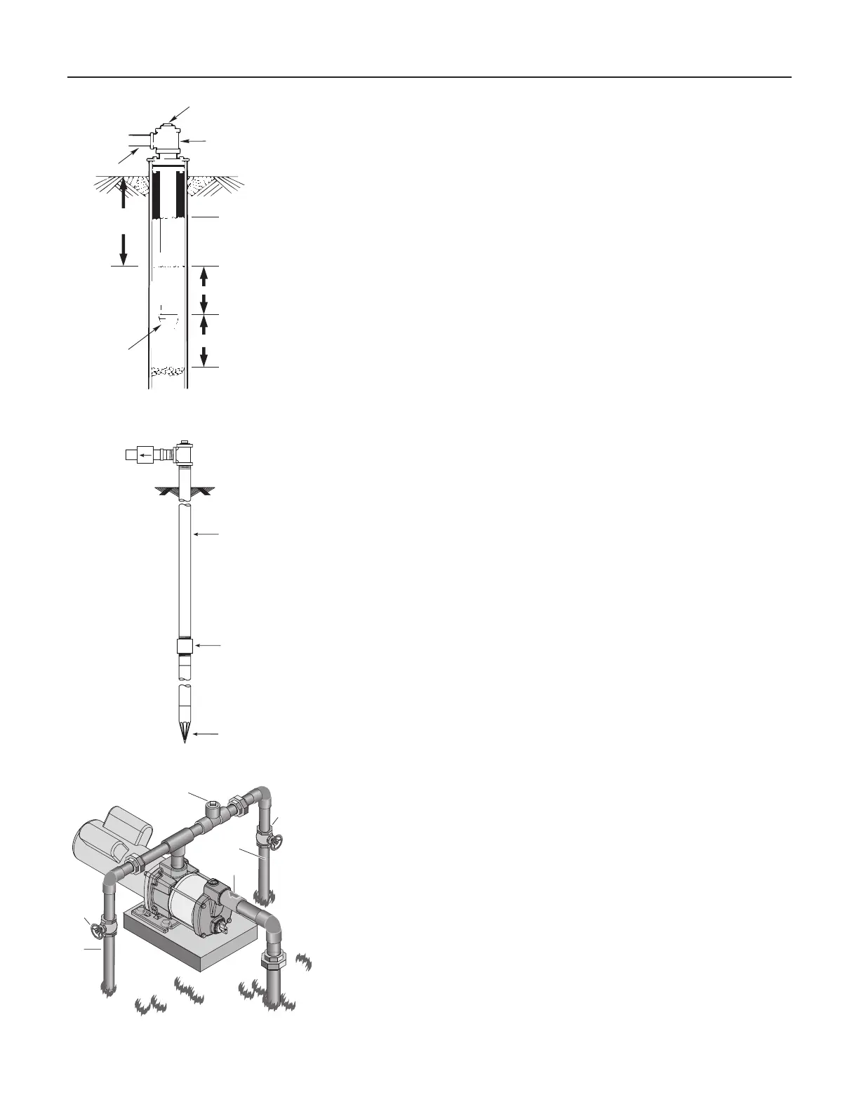
Cased Well Installation
1. Inspect foot valve to be sure it works freely. Inspect strainer to be sure it
is clean.
2. Connect foot valve and strainer to the first length of suction pipe and
lowerpipeintowell.Addsectionsofpipeasneeded,usingPTFEtape
onmalethreads.Besurethatallsuctionpipeisleakprooforpump
will lose prime and fail to pump. Install foot valve 10 to 20 feet below
the lowest level to which water will drop while pump is operating
(pumpingwaterlevel).Yourwelldrillercanfurnishthisinformation.
3. To prevent sand and sediment from entering the pumping system, the
foot valve/strainer should be at least 5 feet above the bottom of the well.
4. When the proper depth is reached, install a sanitary well seal over the
pipe and in the well casing. Tighten the bolts to seal the casing.
5. When using a foot valve, a priming tee and plug as shown in Figure 5
are recommended.
Dug Well Installation
Same as cased well installation.
Driven Point Installation
1. Connect the suction pipe to the drive point as illustrated in Figure6.
Keephorizontalpiperunasshortaspossible.UsePTFEpipethread
sealanttapeonmalepipethreads.Multiplewellpointsmaybe
necessary to provide sufficient water to pump.
2. Install a check valve in horizontal pipe. Flow arrow on check valve
must point toward pump.
Horizontal Piping From Well To Pump
1. Neverinstallasuctionpipethatissmallerthanthesuctionportof
thepump.
2. To aid priming on well point installations, install a line check valve as
showninFigure6.Besurecheckvalveflowarrowpointstowardpump.
Discharge Pipe Sizes
1. If increasing discharge pipe size, install reducer in pump discharge port.
Do not increase pipe size by stages.
2. When the pump is set away from the points of water use, the discharge
pipe size should be increased to reduce pressure losses caused
byfriction.
• Upto100’run:Samesizeaspumpdischargeport.
• 100’to300’run:Increaseonepipesize.
• 300’to600’run:Increasetwopipesizes.
Sprinkling Application
This pump is de signed to deliver plenty of water at full sprinkler pres sure. It can
pump from a pond, cistern or well points.
Pump discharge can be divided to supply two (2) or more sprinkler systems.
A suggested multiple dis charge to service is shown in Figure 7.
Do not use in a pressure tank or booster pump application.
Figure 5 – Cased/Dug Well Installation
Suction
pipe
Foot
Valve
Priming tee
Standing water
level (pump off)
Drawdown water
level (pump on)
10-20' (3-6 m)
20' (6 m) max.
At least 5 feet (1.5 m)
Figure 6 – Driven Point Installation
Check valve
Steel drive pipe
Drive coupling
Driven point
Figure 7 – Multiple Discharge
4326 0203
Gate
Valve
Gate
Valve
To
Service
To
Service
Plug
Check
Valve
 Loading...