Compact Fieldbus Power Hub,Generic Interface
Specification
2014-10
11
2.2.3 Diagnostic Modules
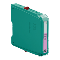
Basic Diagnostic Module
The basic diagnostic module provides basic system diagnostics. It monitors the input voltage
of the bulk power supply and each segment for overload and short circuit conditions. Each
power supply module is checked for proper function. Power modules operating in redundant
configuration are checked for compatibility. LEDs indicate both status and fault information.
This information can be transmitted via volt-free contact.
For further information refer to the instructions "Basic Diagnostic Module HD2-DM-B".
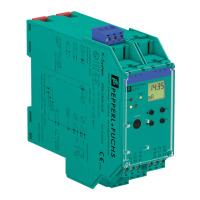
Advanced Diagnostic Module
The advanced diagnostic module is a comprehensive measurement tool for the fieldbus
physical layer. It is well suited for commissioning, online monitoring and maintenance. The
module provides the exact segment and individual device data needed for detection of
changes in the fieldbus physical layer. Segment measurements include fieldbus voltage and
load current; device-specific measurements are: signal level, noise, and jitter. All data is
transmitted to the control room via Ethernet. The Diagnostic Manager – Basic Edition shows all
data on easy-to-use displays.
The Diagnostic Manager – Professional Edition offers extra functionality: the commissioning
wizard generates automated reports; the software displays clear text messages for
troubleshooting of out-of-specification behavior. The OPC server transmits user-selectable
common alarms to the process control system.
For further information refer to the manual "Advanced Diagnostic Module HD2-DM-A".
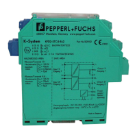
Advanced Diagnostic Module Relay Contact Output
The advanced diagnostic module relay contact output is a tool for permanently monitoring the
fieldbus physical layer. Using DIP switches, limit ranges can be configured for each physical
layer parameter monitored.
The module distinguishes between 2 alarm types:
■ Maintenance required alarm
■ Out of specification alarm
The "Maintenance required" alarm enables proactive diagnostics. If a value exceeds the limit, a
relay contact opens and the respective segment LED starts to flash yellow. With this proactive
diagnostics, changes within the fieldbus installation can be detected early and fault sources
can be found before communication fails.
If an "Out of specification" alarm occurs (LED flashing red) that means: One of the monitored
physical layer parameters has rapidly declined and moved out of range of "Maintenance
required". A fast examination of the affected segment is crucial to prevent a total dropout of this
segment in the near future.
In order to set the appropriate limit values for your fieldbus installation during commissioning, a
comprehensive diagnostic solution is required. For DIP switch configuration, you can use the
mobile advanced diagnostic module.
For further information refer to the manual "Advanced Diagnostic Module HD2-DM-A.RO".
 Loading...