Compact Fieldbus Power Hub,Generic Interface
Installation and Commissioning
2014-10
17
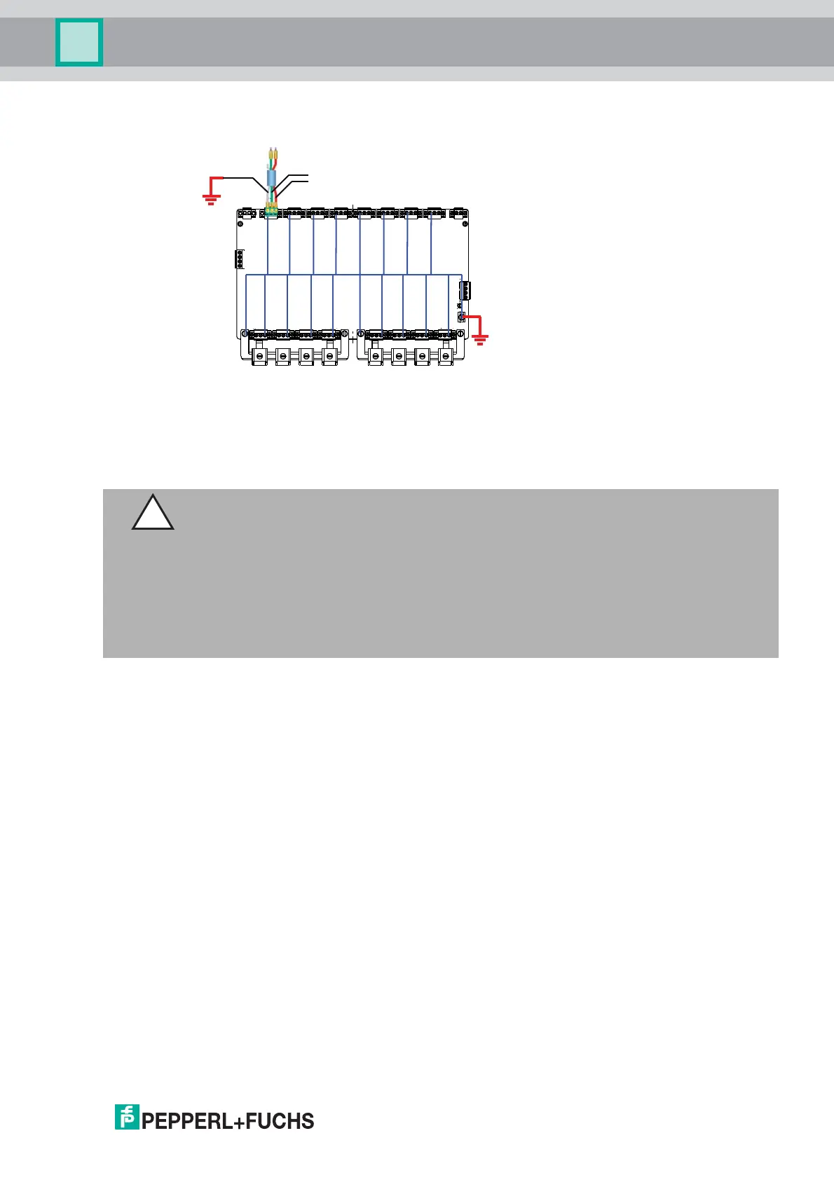
3.3 Shielding and Grounding
Prevent Grounding Loops
Depending on the chosen grounding method, the shield ground at the host connection can be
left open.
In order to prevent a grounding loop if the grounding points of the host and the field devices do
not have the same potential: Leave the shield of the motherboard open.
3.4 Connection Layout
The following section describes the different connection details of the motherboard with
particular reference to the torques required for a safe installation.
For any terminal connections, observe the following cable and connection information.
Screw Terminals: Cable and Connection Information
■ Permissible wire core section:
- Screw terminals with flexible or rigid wires: 0.2-2.5 mm²
■ Insulation stripping length: 7 mm
■ If you use stranded connectors: Crimp on wire end ferrules
■ Ensure that connectors are mechanically locked
■ Torque required for tightening terminal screws: 0.4-0.5 Nm
Spring Terminals: Cable and Connection Information
■ Permissible wire core section:
- Spring terminals with flexible or rigid wires: 0.5-2.5 mm²
■ Insulation stripping length: 10 mm
■ Ensure that connectors are mechanically locked
■ Torque required for tightening terminal screws: 0.4-0.5 Nm
–
+
Caution!
Risk of electric shock and property damage through inadequate grounding
If you fail to connect all metal parts of the device to protective local earth correctly, this could
result in potential equalization currents. These currents could hurt operating personnel or
cause property damage.
The grounding terminal is not a safety earth: Do not use the grounding terminal to ground
exposed metal parts.
Ground exposed metal parts of the device separately. Ensure that a correct grounding is
guaranteed at all times.
 Loading...