Installing your Lambda Spectrometer . 53
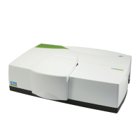
Figure 22 Sipper electrical connection
Pin Configuration
There are two 15-pin connectors fitted to the connector panel of the high-performance
Lambda spectrometer for the connection of accessories. The connectors are identically
configured so that the accessories can be connected to any of them. The pin numbering is
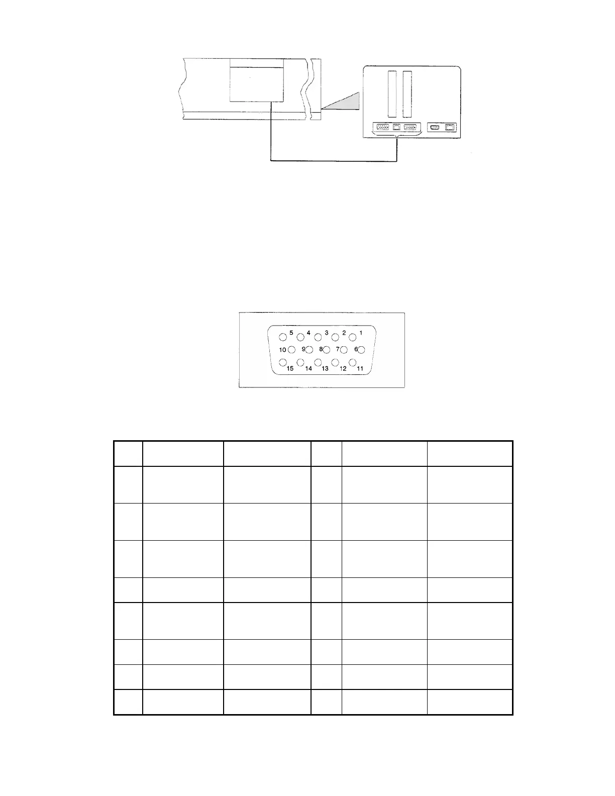
shown in Figure 23, and the configuration is given in the following table.
Figure 23 Pin configuration of 15-pin connector
Pin Configuration Description Pin Configuration Description
1 GND D Ground (Digital)
logic
9 Not used
2 +5 V Logic power
supply
10 Not used
3 Not used 11 +12 V Analog power
supply
4 GND P Ground Power 12 GND A Ground Analog
5 +24 V Power Supply 13 -12 V Analog power
supply
6 Not used 14 SCL Serial clock
7 Not used 15 SDA Serial data
8 Not used
connector panel
 Loading...