Technical Specifications, Connections, and Chassis Overview
EN 2 LC4.3HE AA1.
1. Technical Specifications, Connections, and Chassis Overview
Index of this chapter:
1.1 Technical Specifications
1.2 Connection Overview
1.3 Chassis Overview
Notes:
• Only information that is related to the iTV module, is
published in this manual. For the other information, see the
relevant chassis manual (order code on front page).
• Some models in this chassis range have a different
mechanical construction. The information given here is
therefore model specific.
• Figures below can deviate slightly from the actual situation,
due to the different set executions.
• Specifications are indicative (subject to change).
1.1 Technical Specifications
1.1.1 Vision
Display type : LCD WXGA Active
Matrix TFT
Screen size :
- 26HF5473/10 : 26” (66 cm), 16:9
- 32HF7473/10 : 32” (81 cm), 16:9
Resolution (HxV pixels) : 1366 x 768
Contrast ratio : 600:1
Light output (cd/m
2
) : 500
Response time (ms) : 16 (26”), 18 (32”)
Viewing angle (HxV degrees) : 176x176
Tuning system : PLL
Presets/channels : 125
Tuner bands : VHF
: UHF
: S-band
: Hyper-band
TV Colour systems : PAL B/G, D/K, I
: SECAM B/G, D/K, L/L’
Video playback : NTSC, PAL, SECAM
Supported computer formats : VGA (640x480)
: MAC (640x480)
: SVGA (800x600)
: XVGA (1024x768)
: WXGA (1280x768)
Supported video formats : 640x480i - 1fH
: 720x576i - 1fH
: 640x480p - 2fH
: 720x576p - 2fH
: 1920x1080i - 2fH
: 1280x720p - 3fH
1.1.2 Sound
Sound systems : FM, NICAM Stereo,
Virtual dolby surround
Maximum power (W
RMS
) : 2 x 5 (26”)
: 2 x 15 (32”)
1.1.3 Miscellaneous
Power supply:
- Mains voltage (V
AC
) : 100 - 250
- Mains frequency (Hz) : 50 / 60
Ambient conditions:
- Temperature range (°C) : +5 to +40
- Maximum humidity : 90% R.H.
Power consumption
- Normal operation (W) : 110 (26”), 120 (32”)
Dimensions (WxHxD cm) : 80.5x47.7x22.2 (26”)
: 92.4x55x22.2 (32”)
Weight (kg) : 18.8 (26”)
: 22 (32”)
1.2 Connection Overview
Note: The following connector colour abbreviations are used
(acc. to DIN/IEC 757): Bk= Black, Bu= Blue, Gn= Green, Gy=
Grey, Rd= Red, Wh= White, and Ye= Yellow.
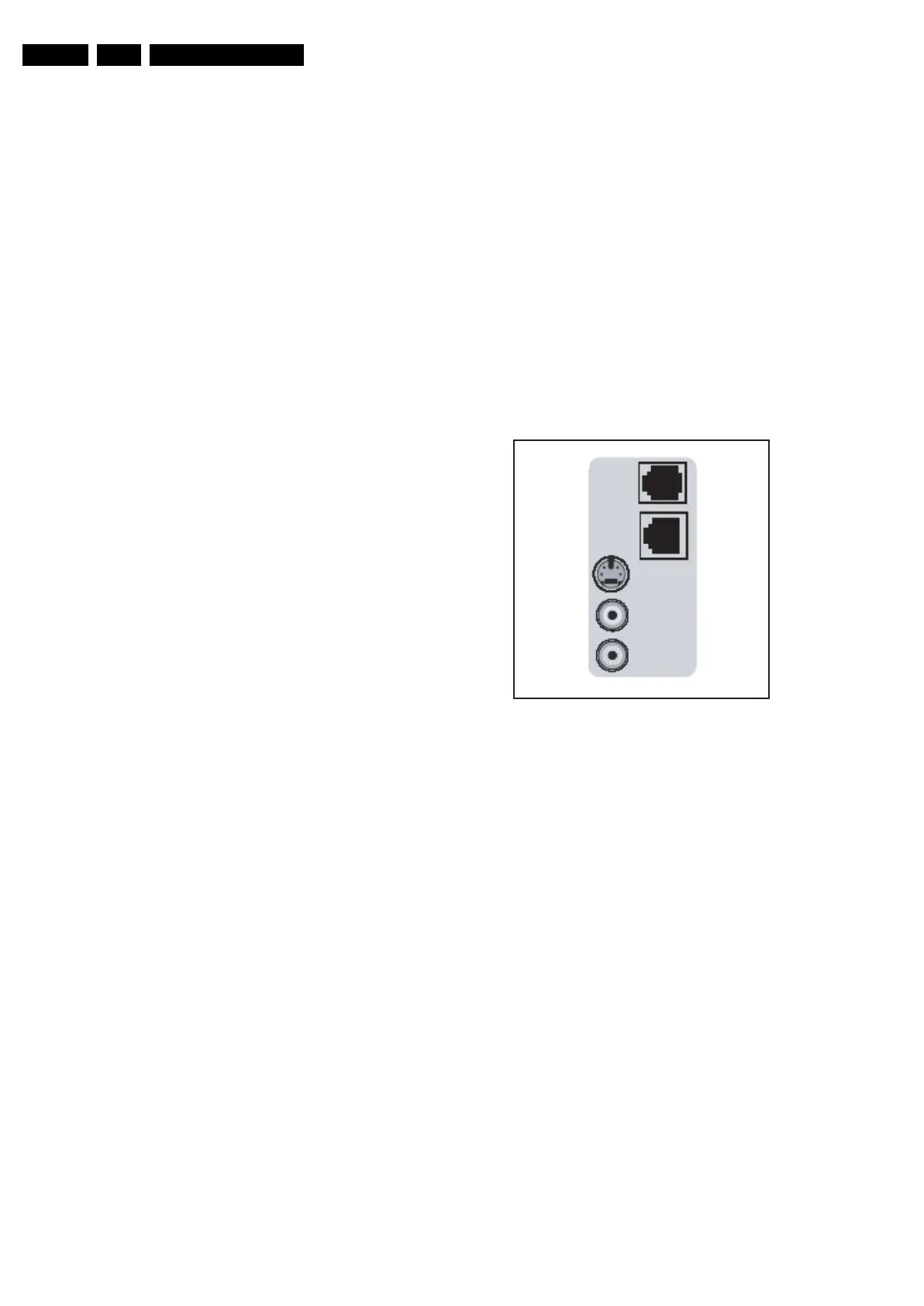
1.2.1 Side I/O connections
Figure 1-1 Side I/O connections
RJ12: DATA1 (HM-Link - In/Out)
1 - LED_in < 0.3 V, active low j
2 - IR_in < 0.3 V, active low j
3-MODE Vcc j
4 - TV Power Status 4.5 to 5 V - TV “On”, < 0.3V -
TV “Stdby”, High impedance -
TV “Off” k
5 - GND Gnd H
6 - IR_out Signal k
RJ45: DATA2 (Xpress Box- In/Out)
1 - +12V +12 V / 1 W k
2 - GND Gnd H
3 - HSYN Signal k
4 - VSYN Signal k
5 - TXD232 Signal
6 - RXD232 Signal
7 - SDA3_IR-OUT Signal k
8 - DCM-POR Signal k
9 - CVBS-terr Signal k
10 - GNDA Gnd H
SVHS (Hosiden): Video Y/C - In
1 - Ground Y Gnd H
2 - Ground C Gnd H
3 - Video Y 1 V
PP
/ 75 ohm j
4 - Video C 0.3 V
PP
/ 75 ohm j
F_15800_020.eps
241105
DATA 1
DATA 2
S-video
AV1 - in
Speaker
 Loading...