onlinecomponents.com
IBSL SYS PRO UM E
1-6 6057AC01
1.3 Structure
1.3.1 Structure of a BK Module With Copper
Connection
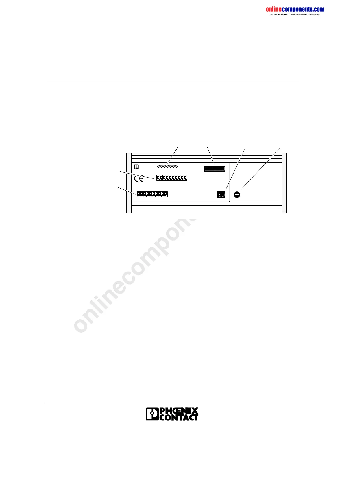
Figure 1-2 Structure of the IBS SL 24 BK-T module
1 Incoming remote bus (INTERBUS IN)
2 Outgoing remote bus (INTERBUS OUT)
3 Diagnostic indicators
4 Connection for the installation local bus
5 Connection of the 24 V power supply for the installation local bus
6 Fuse
U L
R C B A
E
L D
I
N T E R
B
U S
U
S L
6 0 5 7 A 0 0 2
R D
3
4
5
2
1
6
 Loading...