onlinecomponents.com
INTERBUS Loop
6057AC01 1-5
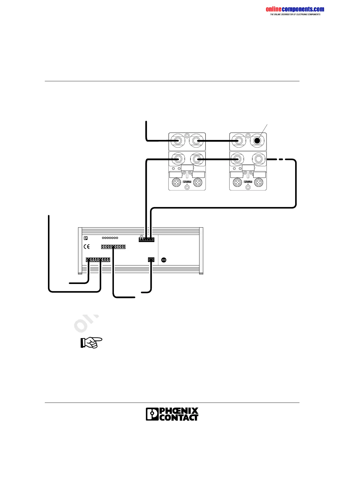
1.2 Installation Example
Figure 1-1 Electrical installation example
Mount the modules on a grounded mounting plate. The modules are
grounded by the mounting screw.
Cover unused sensor/actuator sockets with protective caps (accessories)
to ensure IP 65/IP 67 protection.
Cover the unused connections for the actuator supply with filler plugs
(supplied as standard) and tighten the cap nut to ensure IP 65/IP 67
protection.
U L
R C B A
E
L D
I
N T E R
B
U S
U
S L
I N O U T
R D
R e m o t e b u s
6 0 5 7 A 0 0 1
2 4 V
I B S S L 2 4 B K - T
o r I B S S L 2 4 B K - L K
2 4 V ( i n s t a l l a t i o n l o c a l b u s s u p p l y )
I n s t a l l a t i o n l o c a l b u s r e t u r n
I n s t a l l a t i o n l o c a l b u s f o r w a r d
I N
I N
O U T
I N
O U T
I N
O U T
R e m o t e b u s
I B S L B O X 2 4 D O 2 / 2 M 1 2 - 2 A
2 4 V ( a c t u a t o r s u p p l y )
F i l l e r p l u g s
 Loading...