onlinecomponents.com
INTERBUS Loop
6057AC01 1-9
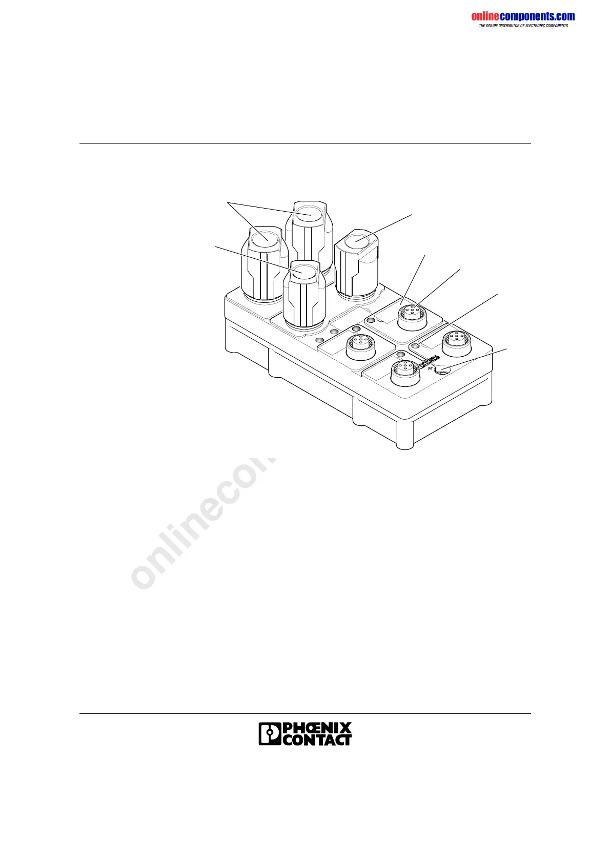
1.3.4 Structure of an INTERBUS Loop Module
Figure 1-5 Structure of an INTERBUS Loop module
1 Incoming installation local bus IN
2 Connection of the 24 V supply voltage for the actuators
3 Outgoing installation local bus OUT
4 Space for labeling plates
5 Sensor/actuator connection
6 Diagnostic and status indicators
7 Functional earth ground connection
6 0 5 7 A 0 0 5
2
1
3
5
7
6
4
 Loading...