onlinecomponents.com
IBSL SYS PRO UM E
1-12 6057AC01
1.4.2 Diagnostic and Status Indicators of the Modules
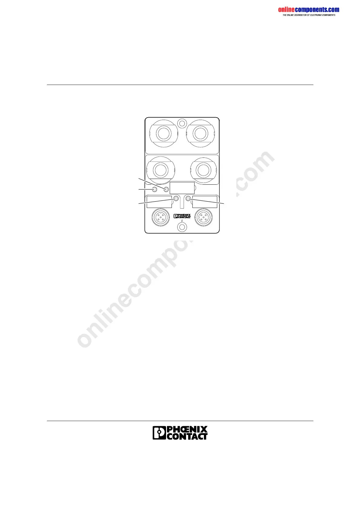
Figure 1-6 Diagnostic and status indicators (example)
Diagnostics The diagnostic LEDs (green) indicate the status of the modules. The
module functions correctly if all of the green LEDs are on.
Status The status of an input/output can be read on the corresponding yellow
LED:
5 1 0 9 B 5 2
D I A G
X 2
X 1
U S
US Green LED
ON:
OFF:
Supply voltage for the actuators
Supply voltage present
Supply voltage not present
– Fuse blown
DIAG Green LED
ON:
Flashing (0.5 Hz):
Flashing (2 Hz):
OFF:
Bus active
Communications power present, bus not
active
I/O error
Communications power not present
X(n) Yellow LED
ON:
OFF:
Status of the input/output
Input/output active, i.e., logic state "1"
Input/output inactive, i.e., logic state "0"
 Loading...